February 9, 2023
Modbus – A Quick Introduction
General InformationModbus
This article is for those of you getting started with Modbus and would like a quick introduction. After reading, you’ll be proficient in the Modbus protocol, and you’ll have enough knowledge to implement Modbus on any platform. We’ll keep things simple, and we’ll be sure to use layman’s terms.
What is it?
Modbus is a communication protocol developed to allow computers to share data with each other in real time. It was originally created in 1979 by a company called Modicon, which is now owned by Schneider Electric. It became extremely popular throughout the years because Modicon openly published the protocol specifications with no royalty fees, thereby allowing device manufacturers to incorporate Modbus into their products free of charge. Dozens of years later, it’s still one of the most used industrial communication protocols.
Overview
Clients and Servers
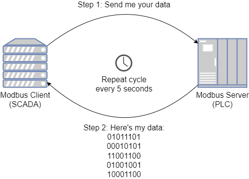
Like most communication protocols, there is a client (sometimes called a master) and a server (sometimes called a slave). The client sends a request to the server, the server processes the request, and then the server issues a response to the client. In most applications, the client is a SCADA system that’s gathering data from a programmable logic controller (PLC). The PLC is the server. The SCADA system will periodically (i.e. every 5 seconds) send a request to the PLC asking for data stored in the PLC’s memory. The PLC will respond with the requested data, and then the SCADA system can display it for the user. Here’s a quick diagram illustrating the concept:
The 3 Types of Modbus
There are 3 different types of Modbus, and Modbus users must be aware of them. However, the architects of Modbus worked hard to keep the foundation of all 3 protocols the same, so the programmers don’t really need to concern themselves too much with the differences. You really just need to know which one to use based on the application you’re implementing. The 3 types of Modbus are Modbus RTU, Modbus ASCII, and Modbus TCP/IP.
Modbus RTU
Modbus RTU was designed for serial communications. It’s used when the client and server are connected via RS232, RS422, or RS485. Its standard specifies things like serial communication settings (parity, stop bits, …). It also defines a device addressing scheme so multiple devices can be connected in the same serial network and distinguish who is being spoken too.
Modbus ASCII
Just like Modbus RTU, Modbus ASCII was designed for serial communications as well. The standard is almost identical to Modbus RTU, with the only difference being data encoding. When Modbus RTU sends data, everything is transmitted as raw binary bits. This is very efficient, however difficult to troubleshoot when viewing data being transmitted. Modbus ASCII sends data as text based characters, which makes things easier to read. However, the drawback is that ASCII requires roughly 2 times the amount of data to be transmitted. It’s recommended to only use Modbus ASCII while troubleshooting and stick to Modbus RTU for production applications.
Modbus TCP/IP
Modbus TCP/IP is used when the client and server are communicating via a TCP/IP network like Ethernet. This is extremely common in today’s world of controls. The protocol specifies additional pieces of information that must be included in Modbus messages to work in a TCP/IP network.
Functions
The client can send several different “types” of requests to the server. The “type” of request sent is chosen based on what the client wants the server to do. For example, if the client wants to read data in the server, the client would send a “read” request. Alternatively, maybe the client wants to update some data in the server. In this case, the client would send a “write” request along with the data to be written. These request “types” are known in the Modbus protocol as functions. Modbus has 21 different functions, each with a special purpose. Most of the time, only 8 of those functions are used and the other 14 are for special use cases. Later on in this article, we’ll provide a breakdown of the 8 most common functions and how to use them.
Data Model
To allow a client to specify what data it wants to read/write in the server, the server maps all its data into “addressable locations” called registers. That way, the client can say “send me the data you’re holding in registers 1-7” or “write 1234 to registers 3-6”. The Modbus data model specifies exactly how the server will organize data into registers.
The data model specifies four types of registers which are described below. Due to the age of the protocol, the names likely won’t have much meaning to modern controls engineers, so it’s recommended to disregard the names and focus mostly on the descriptions:
| Register Type | Description | Allowed Values | Register Bit Size | Modbus Client Permissions |
|---|---|---|---|---|
| Input Discrete | Holds values received by PLC digital input channels | “On” or “Off” | 1 | Read only |
| Coil | Holds values sent to PLC digital output channels | “On” or “Off” | 1 | Read and write |
| Input Register | Holds values received by PLC analog input channels | 0-65535 | 16 | Read only |
| Holding Register | Holds values stored in PLC memory | 0-65535 | 16 | Read and write |
To explain how these register types are used, let’s go through a quick hypothetical example.
Example
Say you’re a PLC programmer and the PLC you’re working on has 4 digital inputs, 4 digital outputs, 2 analog inputs, and 2 setpoints. You’d like the inputs/outputs of the PLC to be visible to a connected SCADA system, and the SCADA system must be able to adjust the setpoints in the PLC.
To accomplish this, you’ll need to map the data points (inputs, outputs, and setpoints) to Modbus registers in the PLC. You can then configure the SCADA system to send read/write requests to the appropriate registers. Let’s start by mapping each PLC data point to a Modbus register as shown below:
| Register Type | Register Address | PLC Data Point |
|---|---|---|
| Input Discrete | 1 | Digital Input 1 |
| Input Discrete | 2 | Digital Input 2 |
| Input Discrete | 3 | Digital Input 3 |
| Input Discrete | 4 | Digital Input 4 |
| Coil | 1 | Digital Output 1 |
| Coil | 2 | Digital Output 2 |
| Coil | 3 | Digital Output 3 |
| Coil | 4 | Digital Output 4 |
| Input Register | 1 | Analog Input 1 |
| Input Register | 2 | Analog Input 2 |
| Holding Register | 1 | Setpoint 1 |
| Holding Register | 1 | Setpoint 2 |
As side note, please be aware that many PLC’s utilize something known as a “Modbus prefix”. Instead of listing the register type, a number corresponding to the register type is prefixed in front of the register address. Common convention is that input discrete has a prefix of 1, coil has a prefix of 0, input register has a prefix of 3, and holding register has a prefix of 4. This convention is not actually part of the Modbus standard, but it is heavily utilized by the Modicon line of PLCs. Using the Modbus prefix convention, the Modbus register map can be rewritten as follows.
| Register Address | PLC Data Point |
|---|---|
| 1×1 | Digital Input 1 |
| 1×2 | Digital Input 2 |
| 1×3 | Digital Input 3 |
| 1×4 | Digital Input 4 |
| 0x1 | Digital Output 1 |
| 0x2 | Digital Output 2 |
| 0x3 | Digital Output 3 |
| 0x4 | Digital Output 4 |
| 3×1 | Analog Input 1 |
| 3×2 | Analog Input 2 |
| 4×1 | Setpoint 1 |
| 4×1 | Setpoint 2 |
Please keep in mind, there’s more than one approach to use when setting up a Modbus register map. Instead of using Modbus register addresses 1-4 for the digital inputs, I could have chosen 2, 4, 6, and 8. Generally speaking, selecting addresses is arbitrary and does not matter. However, for performance reasons that’s out of the scope of this article, it’s best to avoid spacing registers apart. This degrades communication performance.
Modbus Function Codes
Now that you understand what Modbus functions are, and how they’re used to interact with registers in the server, let’s get into the details of the 8 most popular Modbus functions.
Read Coils (Code 01)
A Modbus client uses this function to read the values of coil registers within the Modbus server. The parameters included by the Modbus client when sending this request are below:
- Starting address
- Quantity of registers
The Modbus server responds with a list of the requested coil values. The list will contain the quantity of registers requested, and the first item in the list will be the value at the start address.
Read Discrete Inputs (Code 02)
A Modbus client uses this function to read the values of discrete input registers within the Modbus server. The parameters included by the Modbus client when sending this request are below:
- Starting address
- Quantity of registers
The Modbus server responds with a list of the requested discrete input values. The list will contain the quantity of registers requested, and the first item in the list will be the value at the start address.
Read Holding Registers (Code 03)
A Modbus client uses this function to read the values of holding registers within the Modbus server. The parameters included by the Modbus client when sending this request are below:
- Starting address
- Quantity of registers
The Modbus server responds with a list of the requested holding register values. The list will contain the quantity of registers requested, and the first item in the list will be the value at the start address.
Read Input Registers (Code 04)
A Modbus client uses this function to read the values of input registers within the Modbus server. The parameters included by the Modbus client when sending this request are below:
- Starting address
- Quantity of registers
The Modbus server responds with a list of the requested input register values. The list will contain the quantity of registers requested, and the first item in the list will be the value at the start address.
Write Single Coil (Code 05)
A Modbus client uses this function to write a coil value within the Modbus server. The parameters included by the Modbus client when sending this request are below:
- Coil address
- Coil value
The Modbus server responds by echoing the request back to the client.
Write Single Register (Code 06)
A Modbus client uses this function to write a holding register value within the Modbus server. The parameters included by the Modbus client when sending this request are below:
- Holding register address
- Holding register value
The Modbus server responds by echoing the request back to the client.
Write Multiple Coils (Code 15)
A Modbus client uses this function to write multiple coil values within the Modbus server. The parameters included by the Modbus client when sending this request are below:
- Starting address
- Quantity of registers
- List of coil values
The Modbus server responds by sending the starting address and quantity of coils that were written too.
Write Multiple Holding Registers (Code 16)
A Modbus client uses this function to write multiple holding register values within the Modbus server. The parameters included by the Modbus client when sending this request are below:
- Starting address
- Quantity of registers
- List of holding register values
The Modbus server responds by sending the starting address and quantity of holding registers that were written too.