
3.5Tutorial
Let’s consider that we have two pumps we want to simulate in SimServe. In order to efficiently view and sort information we will be using a UDT with nested UDTs as displayed below:
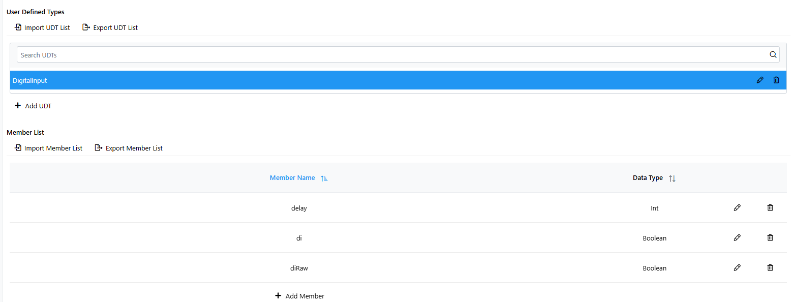
| UDT: DigitalInput | |
|---|---|
| Member | Data Type |
| diRaw | BOOL |
| delay | INT |
| di | BOOL |
| UDT: DigitalAlarm | |
| Member | Data Type |
| alarmDisable | BOOL |
| inAlarm | BOOL |
| alarmDelay | INT |
| di | DigitalInput |
| UDT: AnalogInput | |
| Member | Data Type |
| aiRaw | INT |
| engMin | REAL |
| engMax | REAL |
| aiScaled | REAL |
| UDT: AnalogOutput | |
| Member | Data Type |
| aoScaled | REAL |
| engMin | REAL |
| engMax | REAL |
| aoRaw | INT |
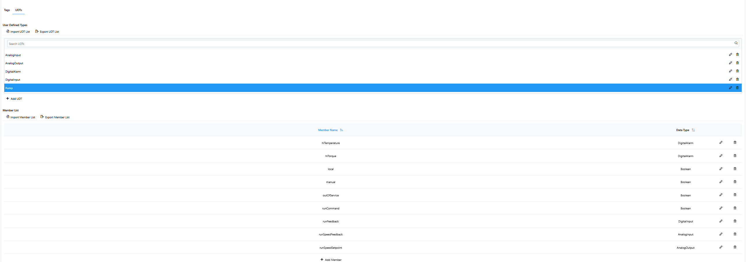
| UDT: Pump | |
| Member | Data Type |
| runCommand | BOOL |
| runFeedback | DigitalInput |
| local | BOOL |
| manual | BOOL |
| outOfService | BOOL |
| hiTorque | DigitalAlarm |
| hiTemperature | DigitalAlarm |
| runSpeedFeedback | AnalogInput |
| runSpeedSetpoint | AnalogOutput |
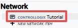
- Start by opening the desired ControlLogix device by double-clicking it.
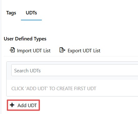
- Navigate to the UDT section and add a new UDT.
- Start by creating the DigitalInput UDT. Continue creation of all other nested UDTs.
- Now using the other UDTs, create the final UDT with the others nested inside of it, as shown:
- Finally, we can create two tags for two different pumps with data type “Pump” to fully simulate the system in SimServe.
