
2.1.1Description
This popup window allows the user to create a new simulated device or gateway within the network. Most options within this menu are specific to the device that is desired to be simulated. In order to ensure an accurate simulation, it is important to configure this pop-up in a manner that reflects the physical network item.
General
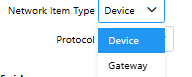
Network Item Type
Gateway: A communication device that translates between Modbus (RTU/ASCII/TCP) and other industrial protocols, allowing legacy serial devices (e.g., RS‑485 sensors or PLCs) to connect to modern Ethernet, SCADA, or IoT systems.
Device: The end-point hardware that holds the Modbus registers being read or written too (e.g., a PLC or sensor).
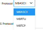
Protocol
MBASCII: Data is sent as readable text, which is slightly slower, over a serial communication line. This is a variant of the Modbus protocol that was created for diagnostic purposes so traffic could be inspected in logs as plain text rather than binary. Devices typically only use the ASCII protocol during initial setup and troubleshooting, and are then switched to the more efficient RTU protocol after.
MBRTU: Data is sent in compact binary form over a serial communication line. This is the primary Modbus serial communication protocol and is used much more frequently compared to Modbus ASCII.
MBTCP: Data is sent through TCP/IP packets over an Ethernet network.
COM Port
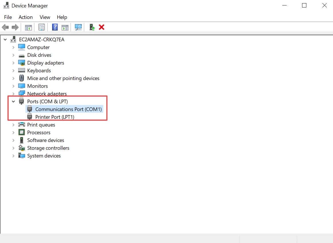
The COM port identifies the serial communication port on the computer that SimServe will use for communication to the device.
On Windows, serial ports are usually labeled as COM1, COM2, COM3, and so on. If a USB-to-serial adapter is used, Windows will assign it a COM port number. The COM port entered must match the exact name Windows displays in the Windows Computer Management dialog box.
Baud Rate
The rate at which data is transmitted over a serial line measured in bits/s. Two devices communicating over different baud rates will not operate properly. Ensure the baud rate set on the device simulated in SimServe matches the baud rate the Modbus master is expecting.
Data Bits
The number of bits used to transmit data per each serial frame. 8 data bits is most common. Ensure the device in SimServe and Modbus master use the same number of data bits.
Stop Bits
Markers sent at the end of each serial frame during serial communication to ensure the receiving device processes the complete serial frame correctly. While 1 stop bit is more common, 2 stop bits can allow for better timing handling with older or slower devices. Ensure the device in SimServe and Modbus master use the same number of stop bits.
Parity
An error handling method in serial communication. With even parity, a parity bit is inserted after the last data bit and before the stop bit. If the number of data bits set to 1 is odd, then the parity bit is set to 1 to ensure an even number of 1 bits is transmitted. With odd parity, if the number of data bits set to 1 is even, the parity bit is set to 1 to ensure an odd number of 1 bits is transmitted. With no parity, the parity bit is not inserted. Ensure the device in SimServe and Modbus master use the same parity.
Device
Slave Address
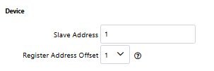
A unique number assigned to each device within a network. When a Modbus master sends a Modbus request on the network, the slave address determines which device should be responding. Each slave address on a bus should be unique. The Modbus standard allows devices to be assigned Modbus addresses 1 to 247. 0 is reserved for broadcast Modbus requests and 248-255 are reserved by the Modbus protocol. However, not all device manufacturers adhere to this standard specified by the Modbus protocol so SimServe will allow addresses in the 1-255 range to be assigned for simulation purposes.
Register Address Offset
The register address offset controls how SimServe translates displayed Modbus addresses into the actual address requested by the Modbus master. Some Modbus masters use address 0 when requesting to read the first Modbus address in the device. However, other Modbus masters use address 1. If the offset is set incorrectly, register values may appear shifted by one address. Use the setting that matches the addressing convention used by the device being simulated.
Bit, Byte, and Word Order
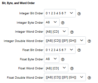
Integer Bit Order
The order in which bits are interpreted within a byte. Each byte contains 8 bits (0-7), with 0 being the least significant and 7 the most significant. The least significant bit most commonly comes first; however, certain devices reverse this order.
The left side of the window (0 in the screenshot) represents the lowest addressed bit, and the right-hand side represents the highest addressed bit. If 07 is selected, 0 is on the left, so the least significant bit is mapped to the lowest addressed bit and the most significant bit is assigned to the highest addressed bit. 70 means the opposite (the lowest addressed bit holds the most significant bit).
This same logic applies to all orders, just with different units of data. Remember that the order in which it is displayed corresponds to addressing, while the number/letter corresponds to significance.
Integer Byte Order
Much like integer bit order, integer byte order determines the sequence in which the most significant byte appears with devices typically running an AB order (with A being least significant and B being most significant).
Integer Word/ Double Word Order
Integer Word and Double Word order follows the same principles as byte and bit order with different scales. An integer word spans 4 bytes (AB CD) while double word spans 8 bytes (AB CD EF GH).
Float Bit, Byte, Word, and Double Word Order
The different float orders follow the same logic as the previous orders, however, float orders can handle both whole and decimal/fractional values (as opposed to integers which can only handle whole values).