
This article is for those getting started with Modbus and looking for a quick introduction. After reading, you'll be proficient in the Modbus protocol and have enough knowledge to implement it on any platform. We'll keep things simple and use plain language.
What is it?
Modbus is a communication protocol developed to allow computers to share data with each other in real time. It was originally created in 1979 by Modicon, now owned by Schneider Electric. It became extremely popular because Modicon openly published the protocol specifications with no royalty fees, so device manufacturers could incorporate Modbus into their products free of charge. Decades later, it's still one of the most used industrial communication protocols.
Overview
Clients and servers
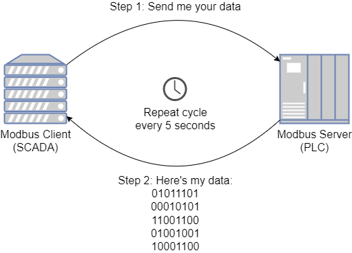
Like most communication protocols, there is a client (sometimes called a master) and a server (sometimes called a slave). The client sends a request to the server, the server processes the request, and the server issues a response to the client.
In most applications the client is a SCADA system gathering data from a PLC. The PLC is the server. The SCADA system will periodically (e.g. every 5 seconds) send a request to the PLC asking for data stored in the PLC's memory. The PLC responds with the requested data, and the SCADA system displays it.
The three types of Modbus
There are 3 different types of Modbus, and Modbus users must be aware of them. The architects worked hard to keep the foundation of all three the same, so programmers don't need to concern themselves with the differences much, you just need to know which one to use based on the application.
Modbus RTU
Modbus RTU was designed for serial communications. It's used when the client and server are connected via RS232, RS422, or RS485. Its standard specifies serial settings (parity, stop bits, …) and a device addressing scheme so multiple devices can share a serial network.
Modbus ASCII
Almost identical to Modbus RTU except that data is encoded as text characters instead of raw binary bits. Easier to troubleshoot by eye, but roughly 2× the bytes on the wire. Use it while troubleshooting; use RTU for production.
Modbus TCP/IP
Modbus TCP/IP is used when the client and server communicate via a TCP/IP network like Ethernet. It's ubiquitous in modern controls. The protocol specifies additional header information required to work in a TCP/IP network.
Functions
The client can send several different "types" of requests. The type chosen depends on what the client wants the server to do, read data, write data, and so on. These request types are called functions. Modbus defines 21 functions; in practice only 8 are used regularly.
Data model
To let a client specify what data it wants to read or write, the server maps its data into addressable locations called registers. The Modbus data model defines four register types. The names are historical, focus on the description:
| Register type | Description | Values | Bits | Client permissions |
|---|---|---|---|---|
| Input Discrete | PLC digital input channels | On/Off | 1 | Read only |
| Coil | PLC digital output channels | On/Off | 1 | Read and write |
| Input Register | PLC analog input channels | 0–65535 | 16 | Read only |
| Holding Register | PLC memory | 0–65535 | 16 | Read and write |
Example
Say a PLC has 4 digital inputs, 4 digital outputs, 2 analog inputs, and 2 setpoints. You'd like the inputs/outputs to be visible to a SCADA system, and the SCADA system must be able to adjust the setpoints. Map each PLC data point to a Modbus register:
| Register type | Address | PLC data point |
|---|---|---|
| Input Discrete | 1 | Digital Input 1 |
| Input Discrete | 2 | Digital Input 2 |
| Input Discrete | 3 | Digital Input 3 |
| Input Discrete | 4 | Digital Input 4 |
| Coil | 1 | Digital Output 1 |
| Coil | 2 | Digital Output 2 |
| Coil | 3 | Digital Output 3 |
| Coil | 4 | Digital Output 4 |
| Input Register | 1 | Analog Input 1 |
| Input Register | 2 | Analog Input 2 |
| Holding Register | 1 | Setpoint 1 |
| Holding Register | 2 | Setpoint 2 |
Many PLCs use a Modbus prefix: instead of listing the register type, a numeric prefix goes in front of the address. Common convention: input discrete = 1, coil = 0, input register = 3, holding register = 4, so 1x1, 0x1, 3x1, 4x1. This convention is not part of the Modbus standard, but it's heavily used by the Modicon PLC line and beyond.
For performance reasons, avoid spacing registers apart with gaps, it degrades communication throughput.
Modbus function codes
The 8 most popular functions:
- 01, Read Coils. Client sends starting address + quantity; server responds with the list of coil values.
- 02, Read Discrete Inputs. Same shape as function 01 but for discrete input registers.
- 03, Read Holding Registers. Starting address + quantity; server responds with holding register values.
- 04, Read Input Registers. Same shape as function 03 but for input registers.
- 05, Write Single Coil. Client sends coil address + value; server echoes the request back.
- 06, Write Single Register. Client sends holding register address + value; server echoes the request back.
- 15, Write Multiple Coils. Client sends starting address, quantity, and coil values; server responds with the starting address and count written.
- 16, Write Multiple Holding Registers. Client sends starting address, quantity, and register values; server responds with the starting address and count written.
Where SimServe fits
Rather than pointing your SCADA at a real PLC just to prove out a register map, spin up a SimServe device with the same map. You get every function code, every register type, and configurable byte/word order, with no field trip required.