February 24, 2023
Connect Ignition to Modbus Device Using Device Simulator
Tutorial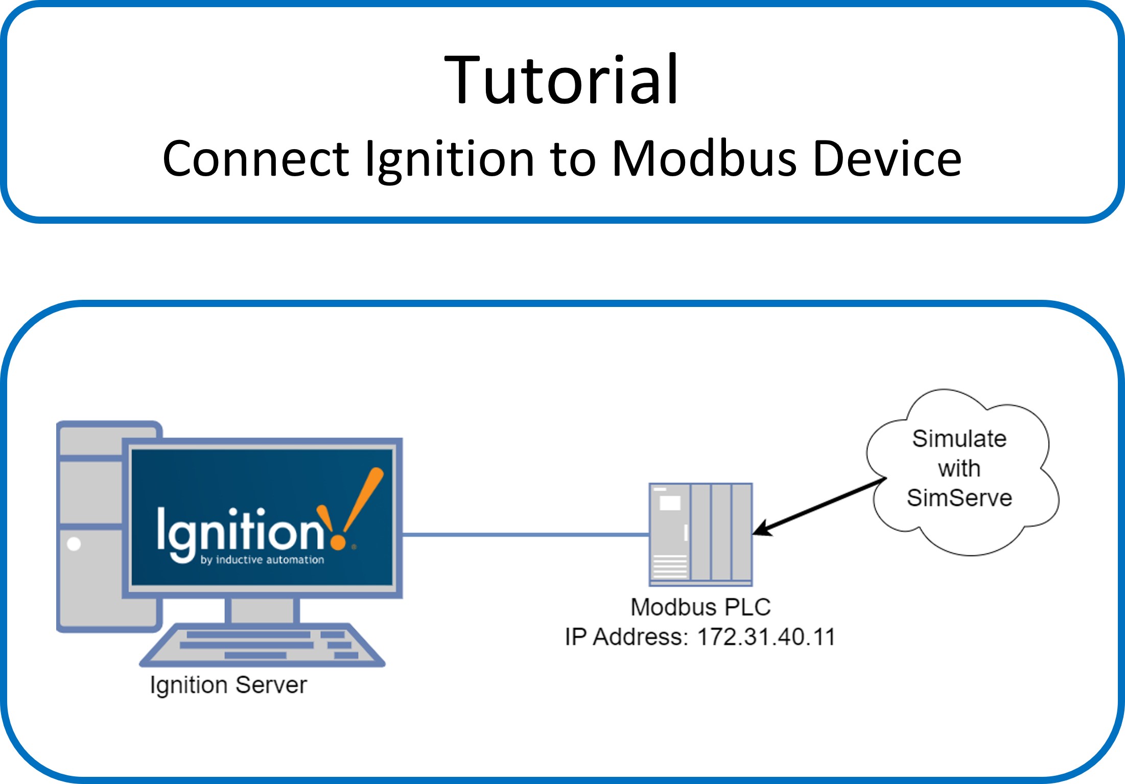
In this tutorial, we’re going to show how to connect Ignition by Inductive Automation to a Modbus TCP/IP device. We’re going to setup tags in Ignition to read the Modbus registers in the device, and we’ll finish with displaying live tag values on an Ignition Perspective HMI screen.
Video Tutorial
For those of you who prefer to watch a tutorial rather than read, please see the video below. If you prefer to read, keep scrolling!
Written Tutorial
Approach
To complete this tutorial, we’re going to use SimServe by SCADAmatic to simulate the Modbus device. SimServe has been installed on a separate computer that’s connected to the same network as Ignition to make the example as realistic as possible. The details of installing SimServe have been omitted in this tutorial, because installation instructions can be found in our documentation center here.
Create the SimServe Project
We’ll start by setting up SimServe to simulate the Modbus TCP/IP device. Begin with a blank project in SimServe:
Click “New Network Item”, and fill out the form that appears as follows:
- Name: Set to “Device01”.
- Protocol: Select “MBTCP” which is short for Modbus TCP.
- IP Address: Set to “0.0.0.0”. This will make the device listen and respond to any Modbus messages sent to any IP address assigned to the computer.
- Leave all remaining fields as default.
- Click “Save”
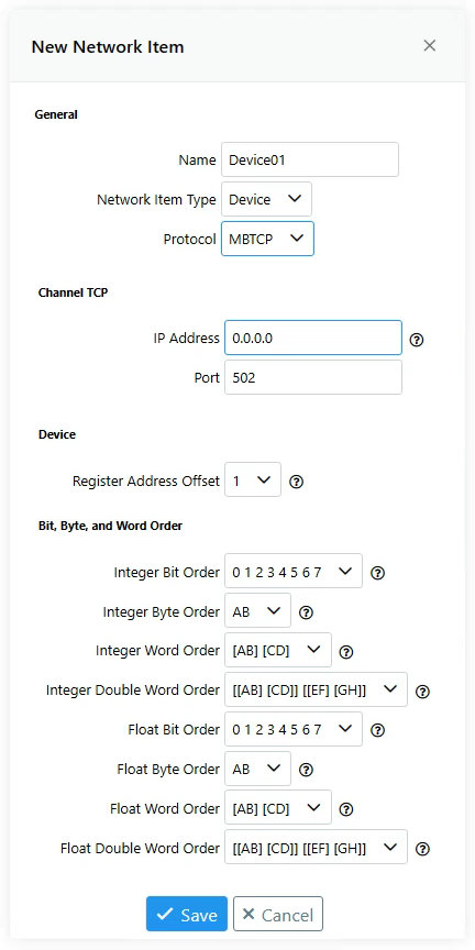
Please note, it may be required to adjust bit, byte, or word order if the computer hosting SimServe has a different order than the computer hosting Ignition. SimServe allows the order to be changed by the dropdowns at the bottom of the form. If you notice the values in Ignition are not the same as values entered into SimServe, that’s an indicator the order needs to be adjusted. You can revisit this topic later after establishing connection between Ignition and SimServe if you observe discrepancies.
The device has now been created and will appear in the network tree.
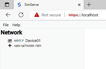
Double click “Device01” in the network tree to view the Modbus device registers.
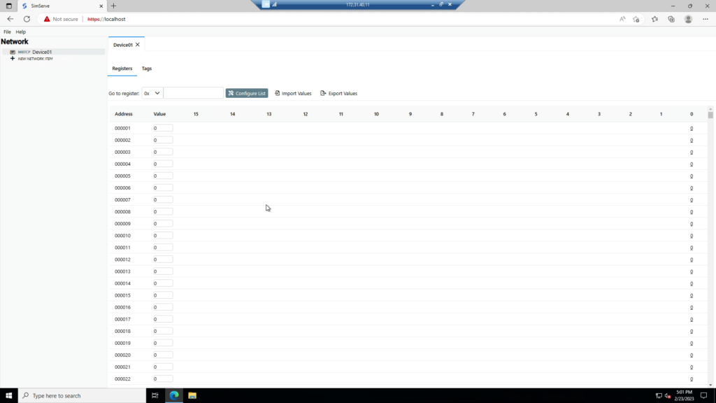
The device is now being Simulated by SimServe, and we can move over to our Ignition server to configure a connection to the Modbus device.
Setup Device Connection in Ignition
Navigate to the Ignition web interface.
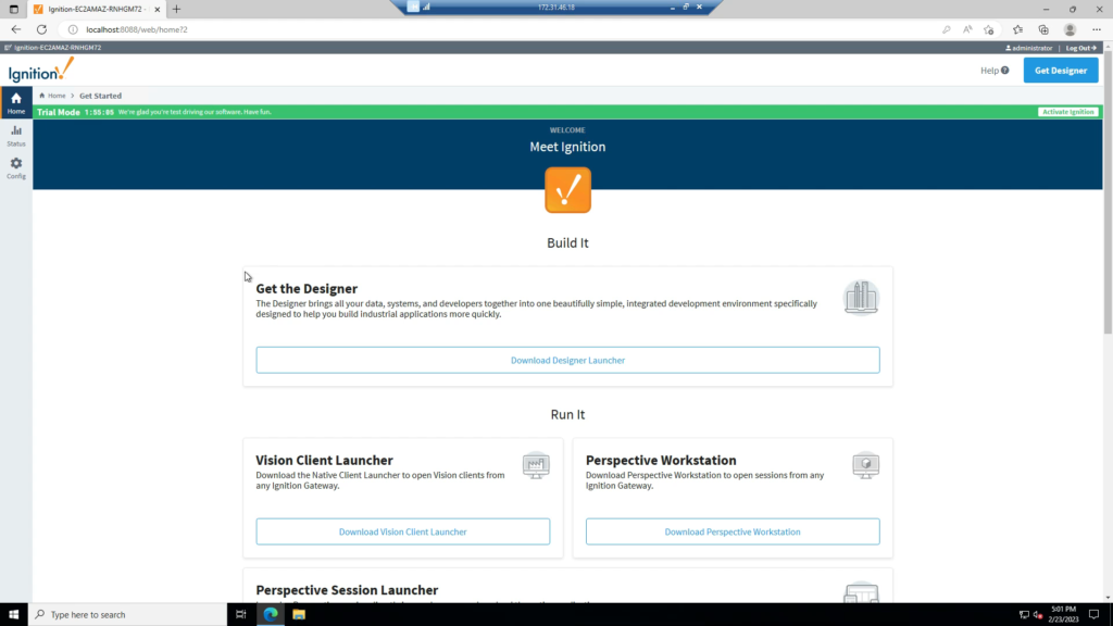
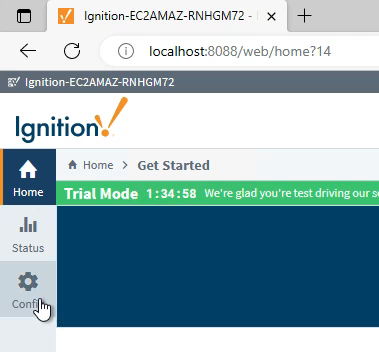
Click on “Config” in the menu on the left-hand side.
Modbus connections are proxied by the Ignition OPC UA server, so scroll down to “OPC UA” and click on “Device Connections”.
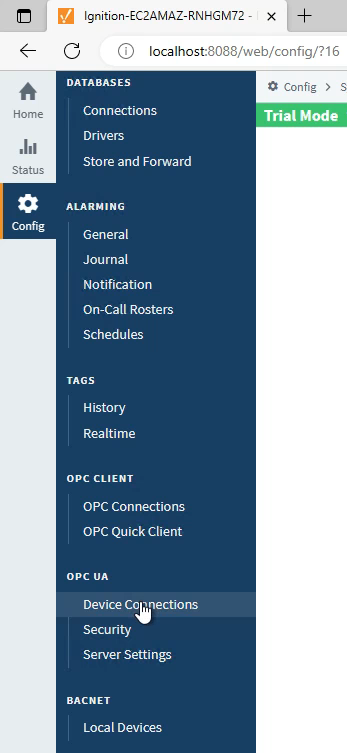
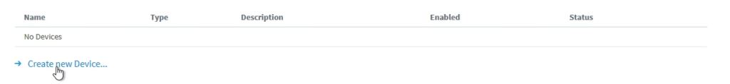
Click on “Create new Device…”
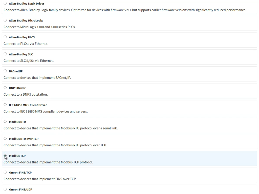
Select “Modbus TCP” and then click on “Next”.
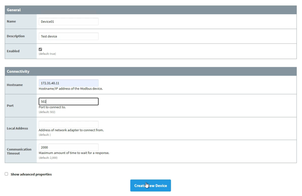
Fill out the form that appears with the information specified below, and then click “Create New Device”:
- Name: Set to “Device01”. This is to keep the name the same in Ignition and SimServe.
- Description: Enter anything you’d like.
- Enabled: Ensure the box is checked.
- Hostname: Enter the IP address of the computer that’s hosting SimServe. In our case, it’s 172.31.40.11.
- Port: Enter the port configured in SimServe for “Device01”. In our case, it’s 502.
- Leave all other fields as default.
After the device is created, you’ll notice “Device01” appears in the table. The most important thing to verify before moving on is that the status column shows “connected”. If it doesn’t show as connected, we know that there is an error in the SimServe setup, a broken network connection between the two computers, or an error in the Ignition device connection settings.

Now that the device connection has been created, we can create some Ignition tags in the HMI designer and link the tags to graphics.
Create Ignition Tags and Test
In preparation for the tutorial, a page has already been created with graphics on it. We just need to create the tags and link to the existing graphics. This has been done because the tutorial is only intended to teach how tags are linked to Modbus registers, and assumes the reader is already familiar with Ignition graphics.
Tag 1: Boolean in 0x1 Register
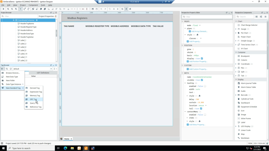
We’ll start out by creating a tag that’s linked to coil register 1 (0x1) in the Modbus device. The tag will communicate to the Modbus device through the “Device01” connection we created in the OPC server, so let’s create an OPC tag.
Click the “+” button in the tag browser, then mouse over “New Standard Tag”, and click on “OPC Tag” as shown.
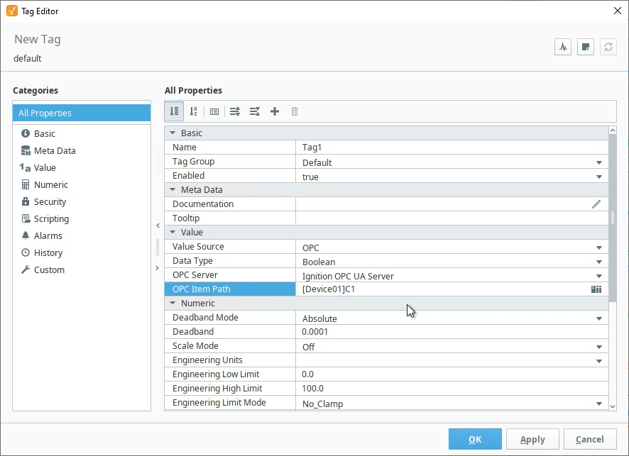
In the tag editor, fill out the form as specified below and click “OK”:
- Name: Tag1
- Data Type: Select “Boolean”. This is because a coil register (1x) only has a single bit.
- OPC Server: Select “Ignition OPC UA Server”, because that’s where the connection for Device01 exists.
- OPC Item Path: This field needs some explanation, as it’s the most important field to understand when linking a tag to a Modbus register. We need to use special syntax that tells the tag to look in Device01 and read a coil register at address 1. The syntax for this case is [Device01]C1:
- [Device01] = Name of Modbus device being read
- C = Coil register (0x)
- 1 = Address 1
- The remainder of this tutorial will be dedicated to showing the creation of several other tags which refer to different Modbus register/data types to teach the syntax. The Ignition user manual provides a good reference of the syntax here.
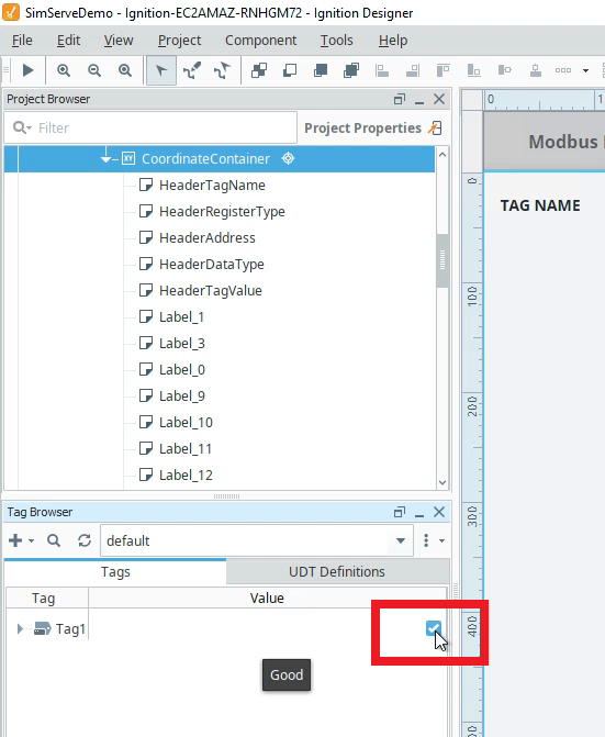
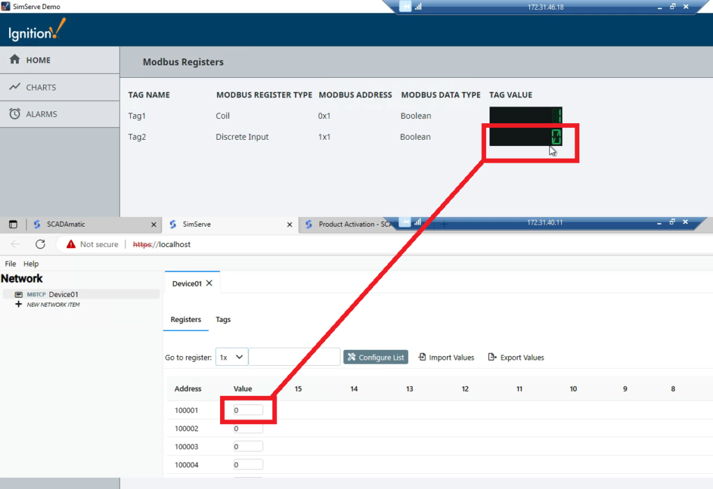
Now that the tag has been created, you’ll see it in the tag browser. There is a value column with a checkbox, and in our case, the box is checked. This is indicating that the Modbus register in the device is currently set to 1.
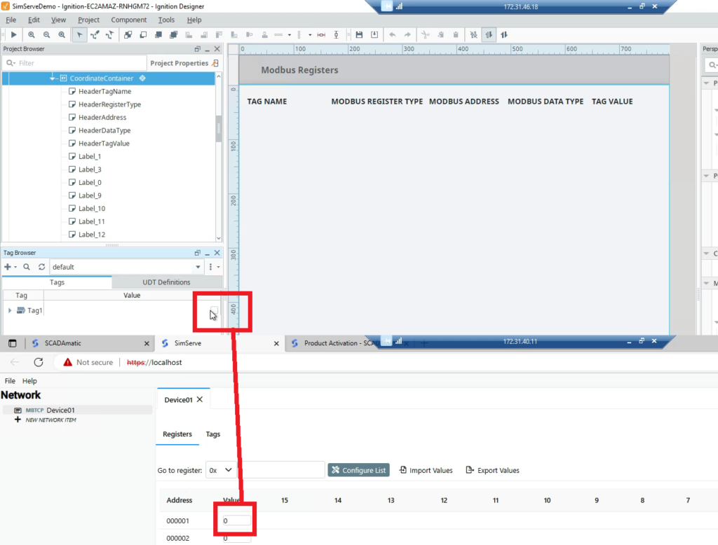
Navigate to the SimServe web interface, open Device01 to view the registers, and look at address 0x1. Toggle the value of the register and verify the checkbox in the Ignition Tag Browser aligns with the register value.
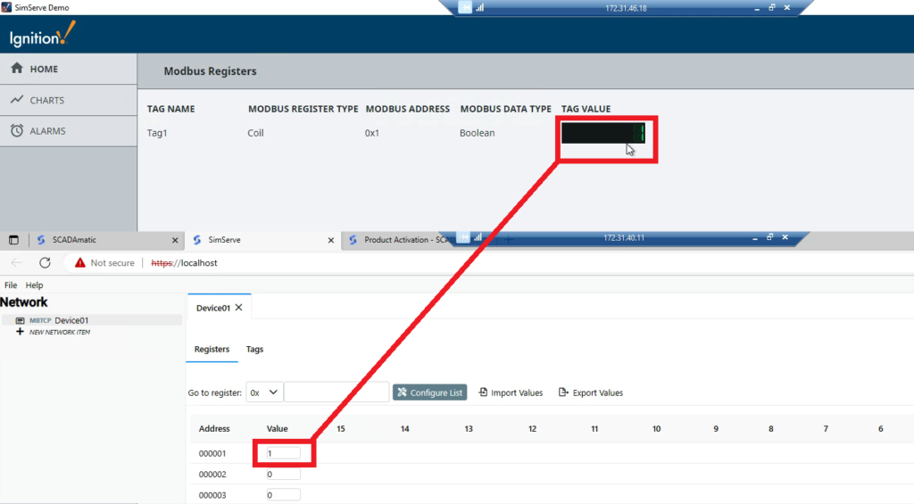
Lastly, we’ll link Tag1 to some graphics and view the tag value at runtime. Then, we’ll toggle the register value in SimServe and observe how the tag value in the HMI changes.
Tag 2: Boolean in 1×1 Register
Now we’ll create a second tag, just like Tag1, except this time we’ll point the tag at discrete input register 1 (1×1). Go to the Ignition HMI designer, create a new standard OPC tag, and fill out the form as shown below:
- Name: Tag2
- Data Type: Select “Boolean”. This is because a discrete input register (1x) only has a single bit.
- OPC Server: Select “Ignition OPC UA Server”.
- OPC Item Path: Enter “[Device01]DI1”.
- [Device01] = Name of Modbus device being read
- DI = Discrete Input register (1x)
- 1 = Address 1

Link Tag2 to graphics in the HMI, view the HMI at runtime, and toggle the value of register 1×1 in SimServe. Observe how the value in the HMI changes.
Tag 3: UInt16 in 3×1 Register
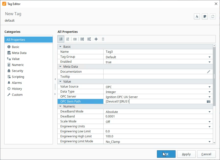
Now we’ll create Tag 3, and we’ll point the tag at analog input register 1 (3×1). Go to the Ignition HMI designer, create a new standard OPC tag, and fill out the form as shown below:
- Name: Tag3
- Data Type: Select “integer”. This is because we’ll have Ignition interpret the binary data in the Modbus registers as an integer number.
- OPC Server: Select “Ignition OPC UA Server”.
- OPC Item Path: Enter “[Device01]IR1”.
- [Device01] = Name of Modbus device being read
- IR = Input register which is another word for analog input register (3x)
- US = Unsigned Short (UInt16)
- 1 = Address 1
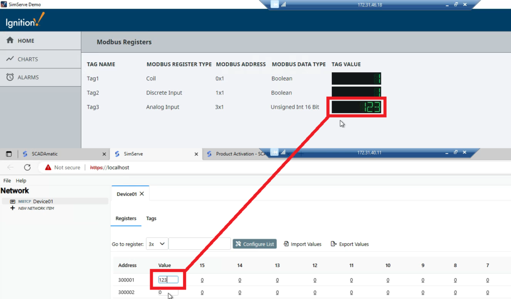
Link Tag3 to graphics in the HMI, view the HMI at runtime, and enter a unique value in register 3×1 in SimServe. Observe the correct value being displayed in the HMI.
Tag 4: UInt32 in 3×2 Register
Now we’ll create Tag 4, and we’ll point the tag at analog input register (3×2). Go to the Ignition HMI designer, create a new standard OPC tag, and fill out the form as shown below:
- Name: Tag4
- Data Type: Select “integer”. This is because we’ll have Ignition interpret the binary data in the Modbus registers as an integer number.
- OPC Server: Select “Ignition OPC UA Server”.
- OPC Item Path: Enter “[Device01]IRUI2”.
- [Device01] = Name of Modbus device being read
- IR = Input register which is another word for analog input register (3x)
- UI = Unsigned Integer (UInt32)
- 2 = Address 2

Link Tag4 to graphics in the HMI, but wait to view in runtime.
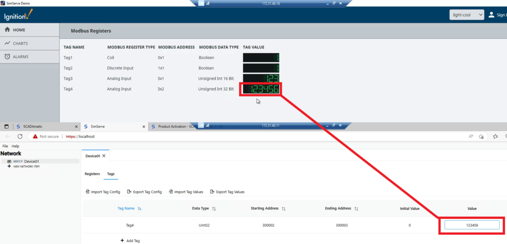
Unlike previous tags we’ve created, this tag is more complicated. The data type we’ve specified in the item path is a 32 bit integer (UInt32). Because analog input registers are only 16 bits in size, this means Ignition will read two analog input registers, starting at 3×2 and ending at 3×3. Ignition will combine the binary bits from both registers into a single integer. This makes it difficult to manually enter register values in SimServe and verify the correct value is displayed in the HMI because Ignition is doing some math to combine registers “behind the scenes”. Luckily, SimServe has the ability to create tags and point them at registers just like Ignition! We’ll use this capability to make testing easier.
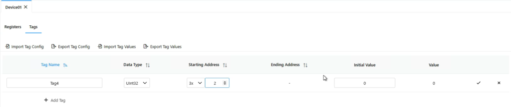
Navigate to SimServe. In the Device01 tab, click on the “Tags” tab. Click on “Add Tag” and fill out the tag form as specified. Then click the check mark:
- Tag Name: Tag4
- Data Type: UInt32
- Starting Address: 3×2
- Initial Value: 0
Enter a unique value for Tag4 in SimServe. Then compare the tag value in SimServe to the Ignition HMI and ensure the value is displayed.
Tag 5: Float in 3×4 Register
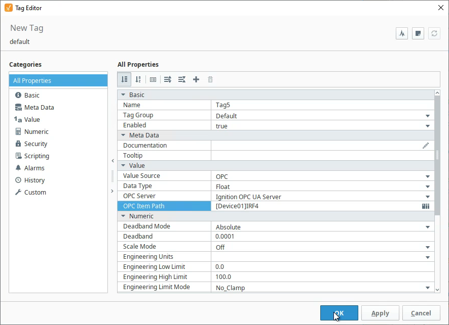
Now we’ll create Tag 5, and we’ll point the tag at analog input register 4 (3×4). Go to the Ignition HMI designer, create a new standard OPC tag, and fill out the form as shown below:
- Name: Tag5
- Data Type: Select “float”. This is because we’ll have Ignition interpret the binary data in the Modbus registers as a decimal number.
- OPC Server: Select “Ignition OPC UA Server”.
- OPC Item Path: Enter “[Device01]IRF4”.
- [Device01] = Name of Modbus device being read
- IR = Input register which is another word for analog input register (3x)
- F = Float
- 4 = Address 4
Link Tag5 to graphics in the HMI.
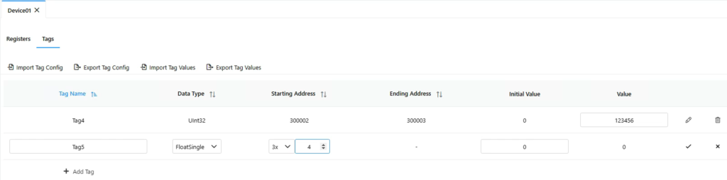
Navigate to SimServe and create Tag5 as specified:
- Tag Name: Tag5
- Data Type: FloatSingle
- Starting Address: 3×4
- Initial Value: 0
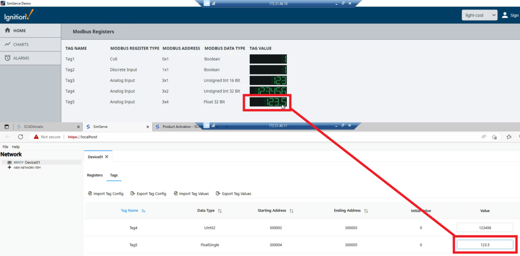
Enter a unique value for Tag5 in SimServe. Then compare the tag value in SimServe to the Ignition HMI and ensure the value is displayed.
Tag 6: SInt16 in 4×1 Register
Now we’ll create Tag 6, and we’ll point the tag at holding register 1 (4×1). Go to the Ignition HMI designer, create a new standard OPC tag, and fill out the form as shown below:
- Name: Tag6
- Data Type: Select “integer”. This is because we’ll have Ignition interpret the binary data in the Modbus registers as an integer number.
- OPC Server: Select “Ignition OPC UA Server”.
- OPC Item Path: Enter “[Device01]HR1”.
- [Device01] = Name of Modbus device being read
- HR = Holding register (4x)
- 1 = Address 1

Link Tag6 to graphics in the HMI.
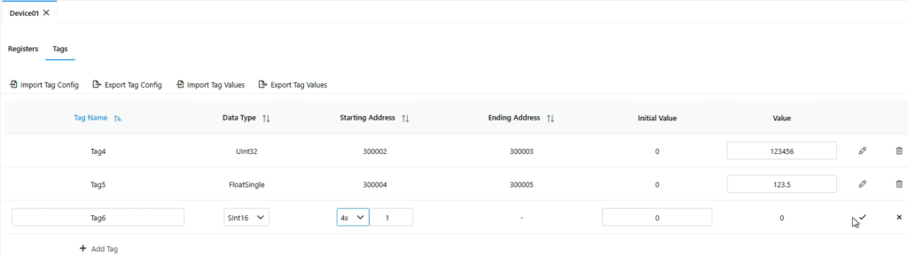
Navigate to SimServe and create Tag6 as specified:
- Tag Name: Tag6
- Data Type: SInt16
- Starting Address: 4×1
- Initial Value: 0
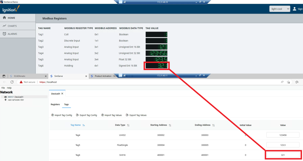
Enter a unique value for Tag6 in SimServe. Then compare the tag value in SimServe to the Ignition HMI and ensure the value is displayed.
Tag 7: SInt32 in 4×2 Register
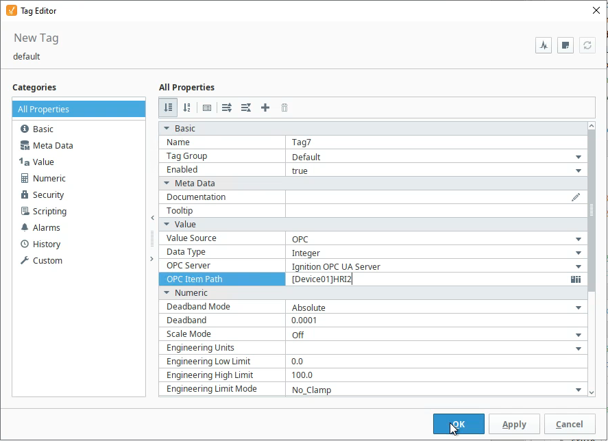
Now we’ll create Tag 7, and we’ll point the tag at holding register 2 (4×2). Go to the Ignition HMI designer, create a new standard OPC tag, and fill out the form as shown below:
- Name: Tag7
- Data Type: Select “integer”. This is because we’ll have Ignition interpret the binary data in the Modbus registers as an integer number.
- OPC Server: Select “Ignition OPC UA Server”.
- OPC Item Path: Enter “[Device01]HRI2”.
- [Device01] = Name of Modbus device being read
- HR = Holding register (4x)
- I = Signed Integer (SInt32)
- 2 = Address 2
Link Tag7 to graphics in the HMI.
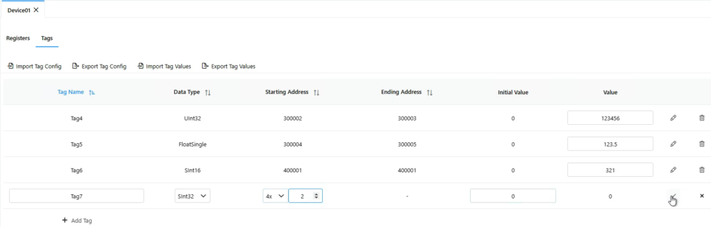
Navigate to SimServe and create Tag7 as specified:
- Tag Name: Tag7
- Data Type: SInt32
- Starting Address: 4×2
- Initial Value: 0
Enter a unique value for Tag7 in SimServe. Then compare the tag value in SimServe to the Ignition HMI and ensure the value is displayed.

Tag 8: FloatDouble in 4×4 Register
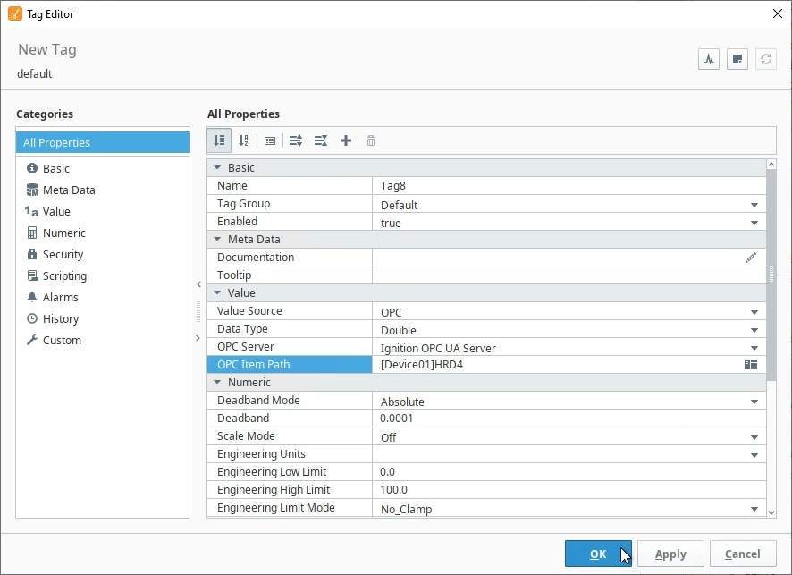
Now we’ll create Tag 8, and we’ll point the tag at holding register 4 (4×4). Go to the Ignition HMI designer, create a new standard OPC tag, and fill out the form as shown below:
- Name: Tag8
- Data Type: Select “double”. This is because we’ll have Ignition interpret the binary data in the Modbus registers as a FloatDouble number.
- OPC Server: Select “Ignition OPC UA Server”.
- OPC Item Path: Enter “[Device01]HRD4”.
- [Device01] = Name of Modbus device being read
- HR = Holding register (4x)
- D = Double (FloatDouble)
- 4 = Address 4
Link Tag8 to graphics in the HMI.
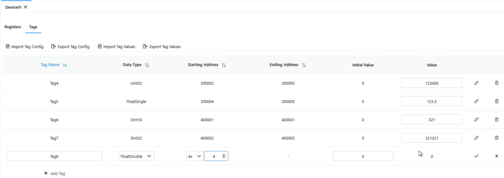
Navigate to SimServe and create Tag8 as specified:
- Tag Name: Tag8
- Data Type: FloatDouble
- Starting Address: 4×4
- Initial Value: 0
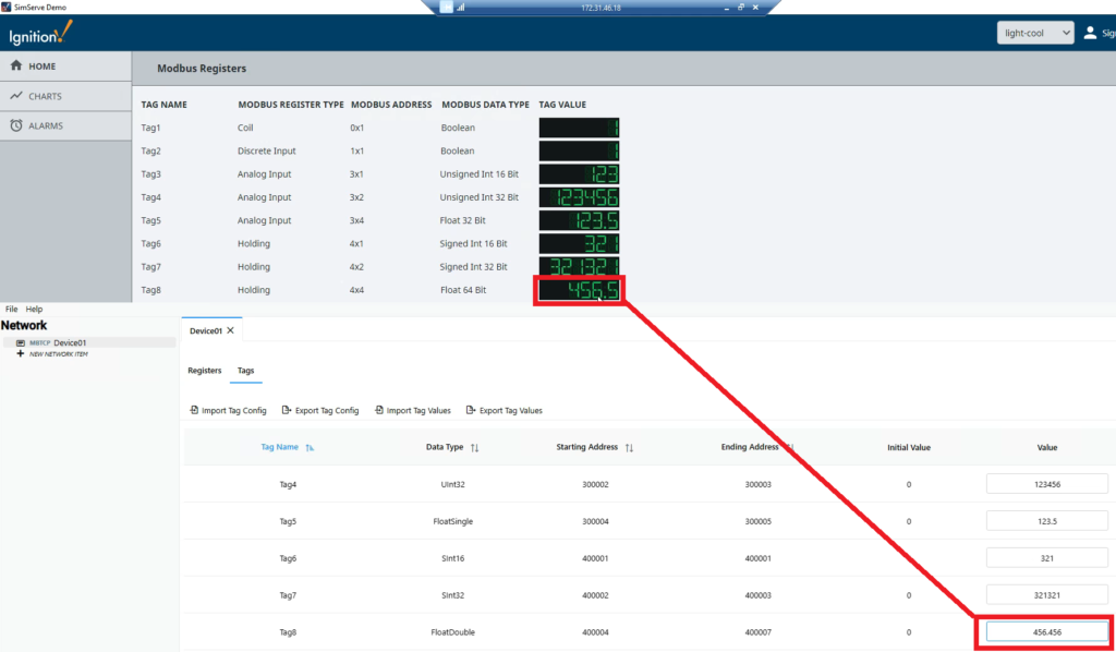
Enter a unique value for Tag8 in SimServe. Then compare the tag value in SimServe to the Ignition HMI and ensure the value is displayed.
Conclusion
I know this was a lengthy tutorial, but hopefully it eliminates some headaches for you in future integration work. Lastly, as the tutorial shows, SimServe is a great tool to help work through Ignition to Modbus integration challenges and we recommend checking it out. Thank you for reading, and please reach out to us at support@scadamatic.com if you have any questions we can assist with.