March 28, 2023
Connect VTScada to Modbus Device Using Device Simulator
Tutorial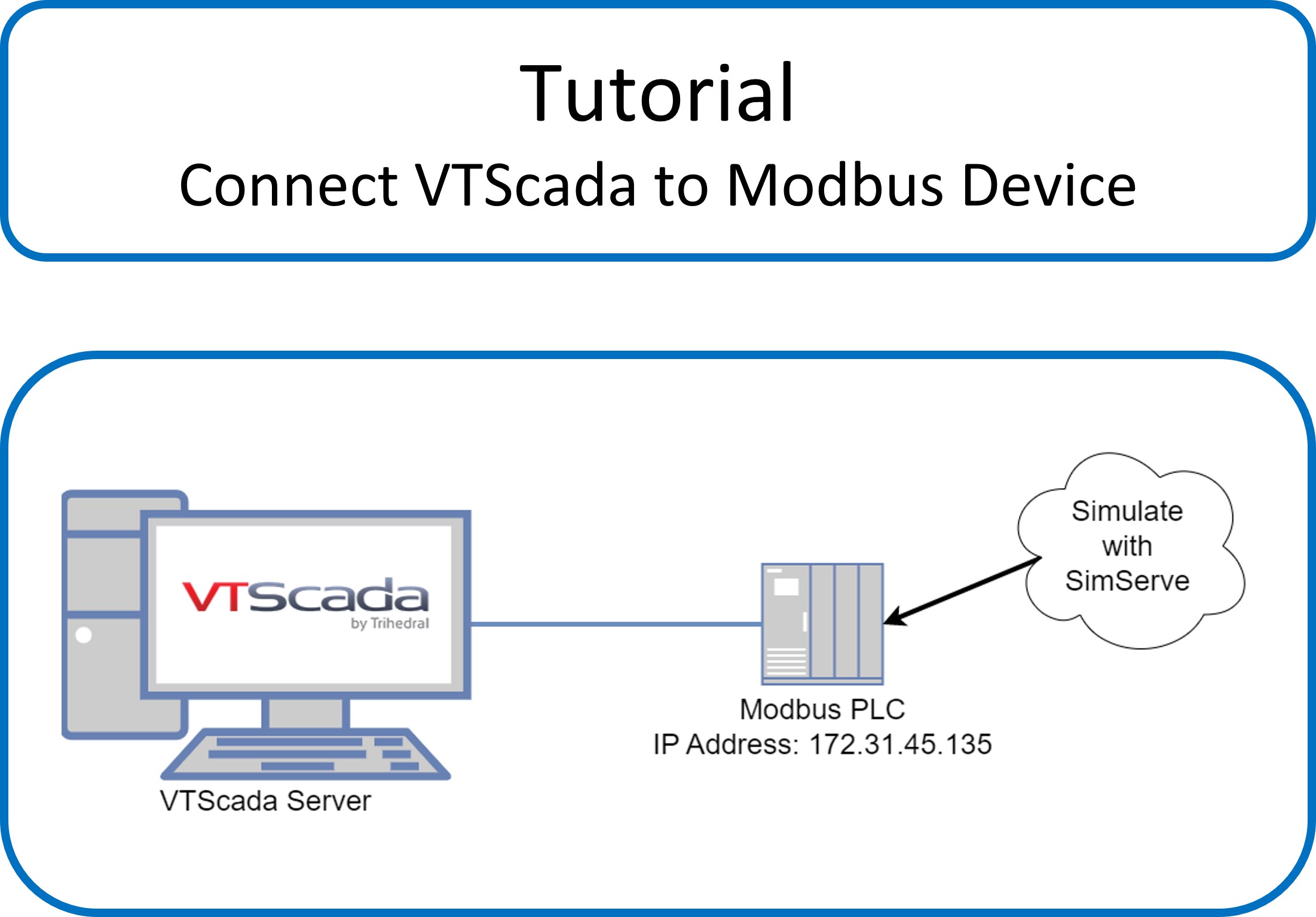
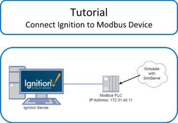
In this tutorial, we’re going to show how to connect VTScada by Trihedral to a Modbus TCP/IP device. We’re going to setup tags in VTScada to read the Modbus registers in the device, and we’ll finish with displaying live tag values on a VTScada HMI screen.
Video Tutorial
For those of you who prefer to watch a tutorial rather than read, please see the video below. If you prefer to read, keep scrolling!
Written Tutorial
To complete this tutorial, we’re going to use SimServe by SCADAmatic to simulate the Modbus device. SimServe has been installed on a separate computer that’s connected to the same network as VTScada to make the example as realistic as possible. The details of installing SimServe have been omitted in this tutorial, because installation instructions can be found in our documentation center here.
Create the SimServe Project
We’ll start by setting up SimServe to simulate the Modbus TCP/IP device. Begin with a blank project in SimServe:
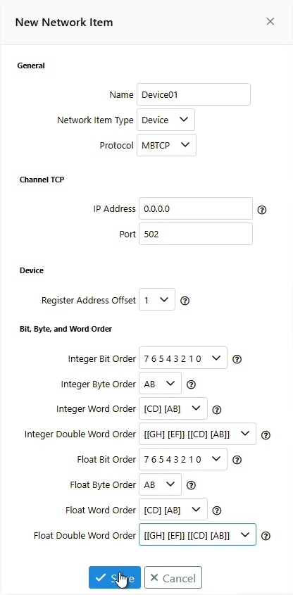
Click “New Network Item”, and fill out the form that appears as follows:
- Name: Set to “Device01”.
- Protocol: Select “MBTCP” which is short for Modbus TCP.
- IP Address: Set to “0.0.0.0”. This will make the device listen and respond to any Modbus messages sent to any IP address assigned to the computer.
- Set the bit order, byte order, word order, and double word order for integers and floats as shown in the screenshot.
- Leave all remaining fields as default.
- Click “Save”
Please note, it may be required to adjust bit, byte, or word order if the computer hosting SimServe has a different order than the computer hosting VTScada. If you notice the values in VTScada are not the same as values entered into SimServe, that’s an indicator the order needs to be adjusted. You can revisit this topic later after establishing connection between VTScada and SimServe if you observe discrepancies.
The device has now been created and will appear in the network tree.
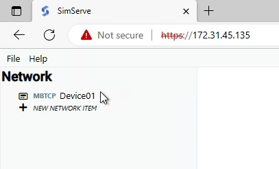
Double click “Device01” in the network tree to view the Modbus device registers.
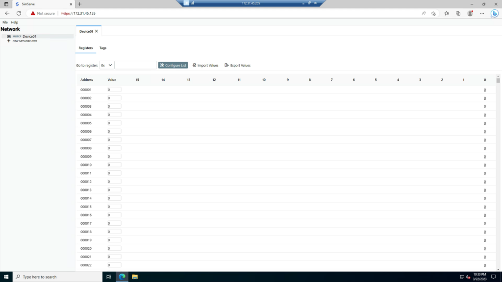
The device is now being Simulated by SimServe, and we can move over to our VTScada server to configure a connection to the Modbus device.
Setup Device Connection in VTScada
We’re now going to setup a connection in a VTScada application to “Device01” in SimServe. Either open an existing or create a new VTScada application. In preparation for the tutorial, an application called “ModbusDemo” was pre-created to eliminate the need to show non-Modbus related tasks (like setting up an HMI page). This has been done because the tutorial is only intended to teach how tags are linked to Modbus registers, and assumes the reader is already familiar with managing VTScada applications and working with VTScada graphics.
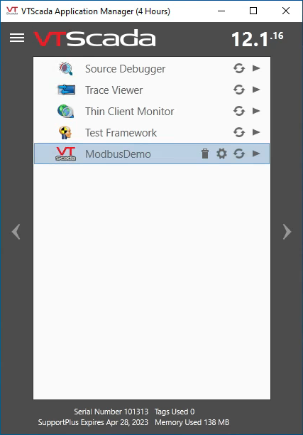
We’ll start by launching VTScada and opening the pre-created “ModbusDemo” application.
To stay organized, before we create the Modbus device connection objects, we’ll create a context called “SimServe” that will hold everything.
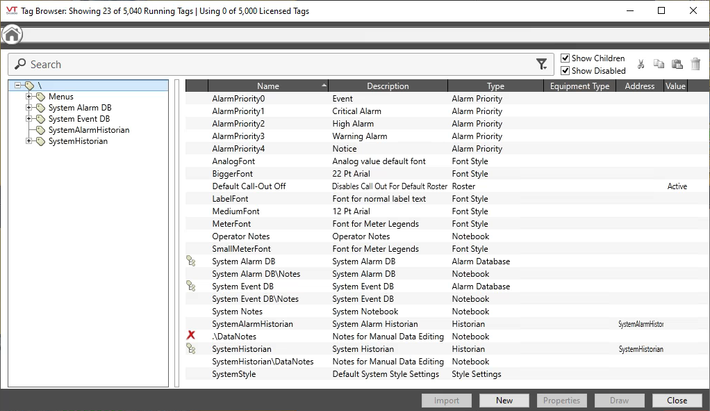
Launch the tag browser.
Right click on the root container, and click “New Child”.
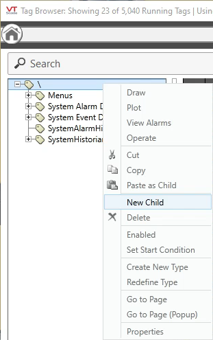
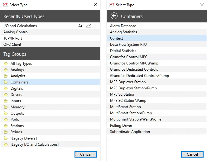
On the “Select Type” popup, click on “Container” and then “Context”.
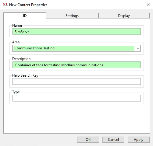
Fill out the ID tab for the new context as follows and click OK:
- Name: SimServe
- Area: Communications Testing
- Description: [Something descriptive]
Now that we’ve got a container to hold everything, we will create what is called the “communication chain” to the Modbus device. Before we dive into the configuration, let’s discuss what a communication chain is.
Communications Chain
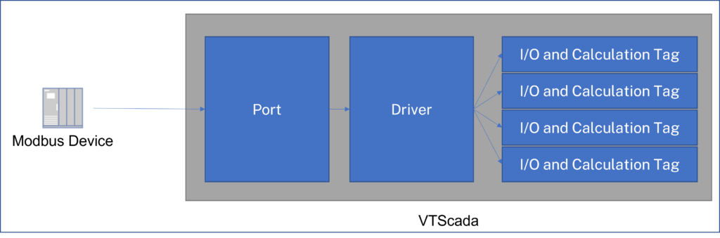
In VTScada, a communications chain consists of three links:
- Port: The port tells VTScada how the physical device is connected
- Driver: The driver tells VTScada which communication protocol to use and allows the user to specify protocol specific settings to communicate with the device.
- I/O and Calculation Tags: The tags hold references to the memory registers in the Modbus device and VTScada reads the register values into the tags.
Information flows from the Modbus device, through the port, to the driver, and data gets stored in the appropriate I/O and Calculation Tags. The diagram below helps illustrate this concept.
Let’s start by creating the port in VTScada. Right click on the “SimServe” context and select “New Child”.
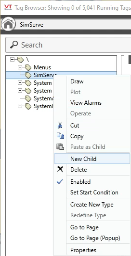
On the “Select Type” popup, click on “Ports” and then “TCP/IP Port”.

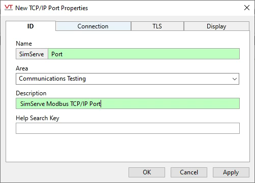
On the “ID” tab, enter the following:
- Name: Port
- Description: SimServe Modbus TCP/IP Port
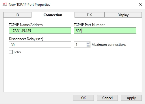
On the “Connection” tab, enter the connection settings to communicate to “Device01” on SimServe as follows and then click OK:
- TCP/IP Name/Address: Enter the IP address of the Modbus device. For us, it’s 172.31.45.135.
- Port: Enter the port the Modbus device is listening for Modbus connections on. For us, it’s 502.
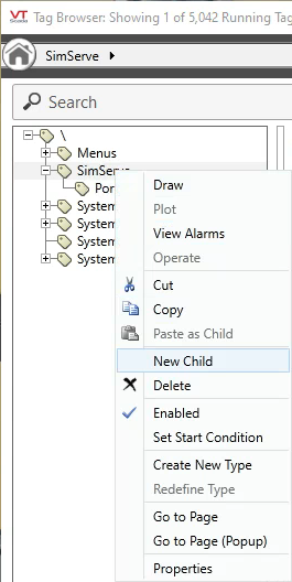
Let’s create the next link in the communications chain, which is the driver. Right click on the “SimServe” context and select “New Child”.
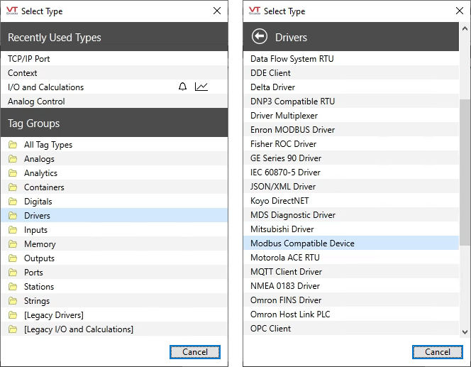
On the “Select Type” popup, click on “Driver” and then “Modbus Compatible Device”.
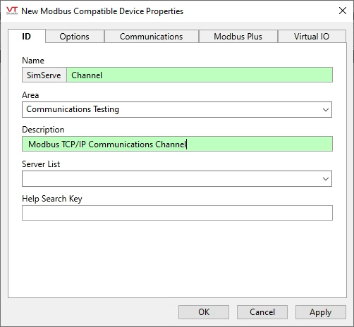
Fill out the “ID” tab as follows:
- Name: Channel
- Description: Modbus TCP/IP Communications Channel
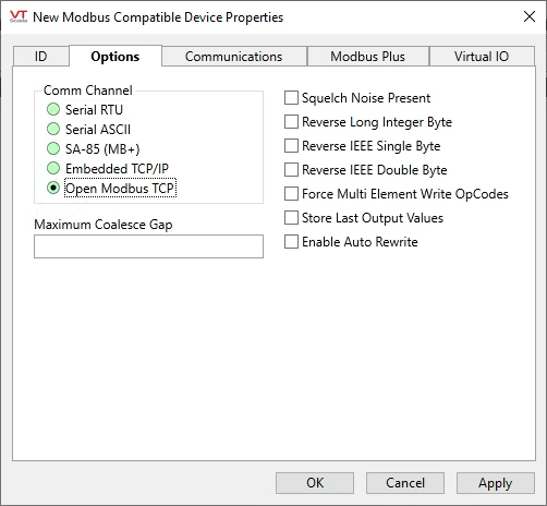
Fill out the “Options” tab as follows:
- Comm Channel: Open Modbus TCP
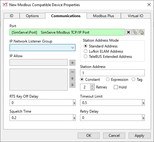
Fill out the “Communications” tab as follows and then click OK:
- Port: Select “SimServe Modbus TCP/IP Port” created already
Now that the first two links of the communications chain have been created (port and driver), we’ll move onto the third link which is the I/O and Calculation tags.
Create VTScada Tags and Test
We’ll be creating tags that are linked to specific Modbus registers in Device01 and will hold a copy of the register values. After we create each tag, we’ll link the tag to graphics in the HMI and view the value at runtime. We’ll ensure the value displayed at runtime matches the value in “Device01” in SimServe.
Tag 1: Boolean in 0x1 Register
Let’s create a tag that’s linked to coil register 1 (0x1) in the Modbus device.
In the Tag Browser, right click the “SimServe” context and select “New Child” as shown.
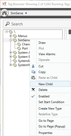
Because a coil register (1x) only has a single bit, and we want the VTScada tag to be the same size as the Modbus register, we’ll create a VTScada “Digital I/O and Calculation” tag.
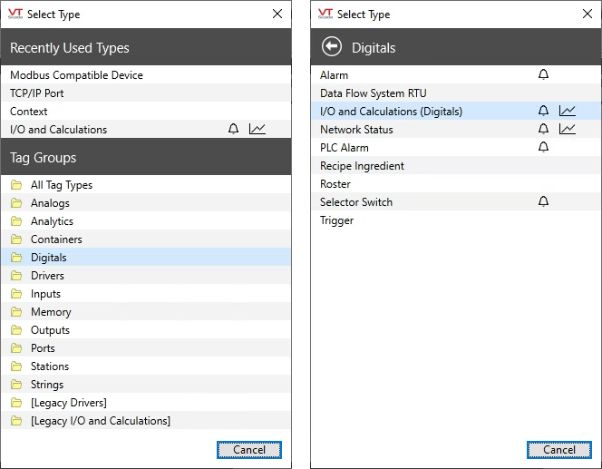
In the “Select Type” popup, click on “Digital” and then “I/O and Calculations (Digitals)”.
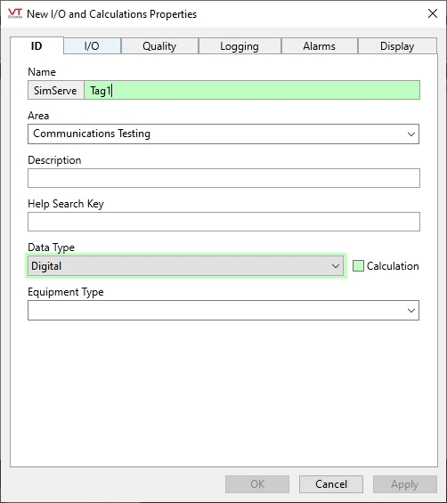
On the “ID” tab, let’s enter a name of “Tag1”
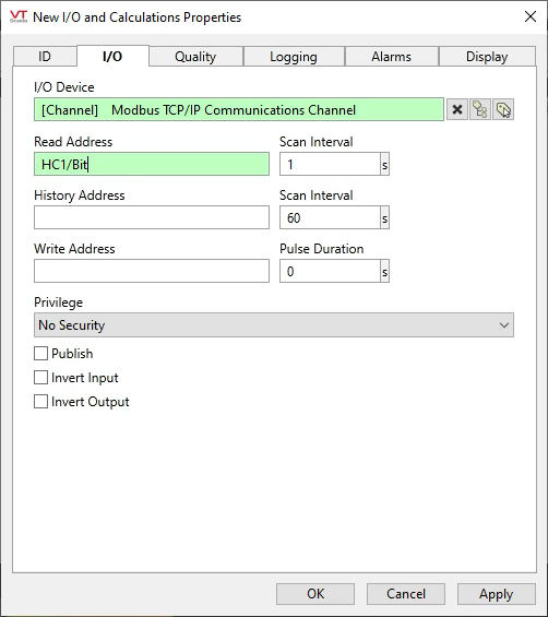
On the “I/O” tab, fill out the form as follows and click OK.
- I/O Device: Select “Modbus TCP/IP Communications Channel” that was previously created.
- Read Address: This field needs some explanation, as it’s the most important field to understand when linking a tag to a Modbus register. We need to use special syntax that tells the tag to read a coil register at address 1. The syntax for this case is “HC1/Bit”:
- HC = “Holding Coil” which is VTScada’s nomenclature for a coil register (0x).
- 1 = Register address 1
- Bit = Data type of the value stored in the Modbus register, which will always be Bit for a coil register
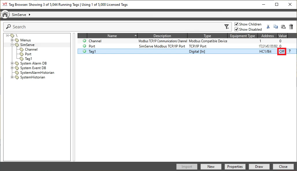
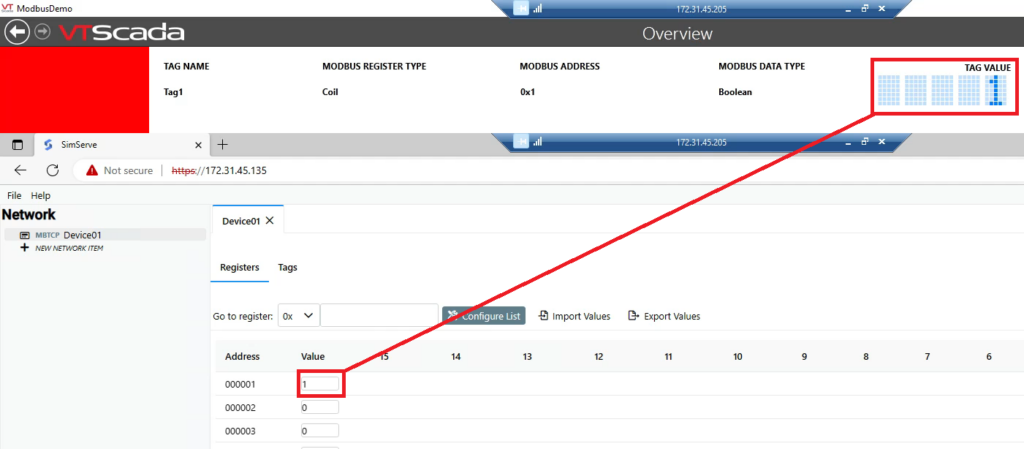
Now that the tag has been created, you’ll see it in the Tag Browser. There is a value column, and in our case, the column shows the word “off”. This is indicating that the Modbus register in the device is currently set to 0.
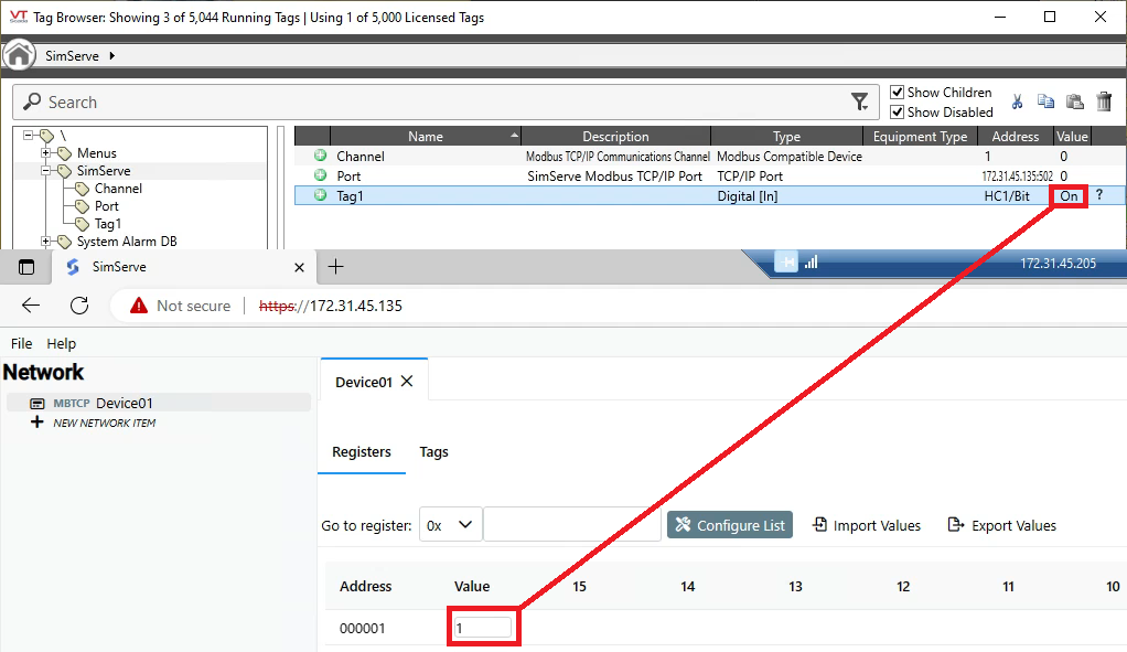
Navigate to the SimServe web interface, open Device01 to view the registers, and look at address 0x1. Toggle the value of the register and verify the tag’s value in VTScada aligns with the register value.
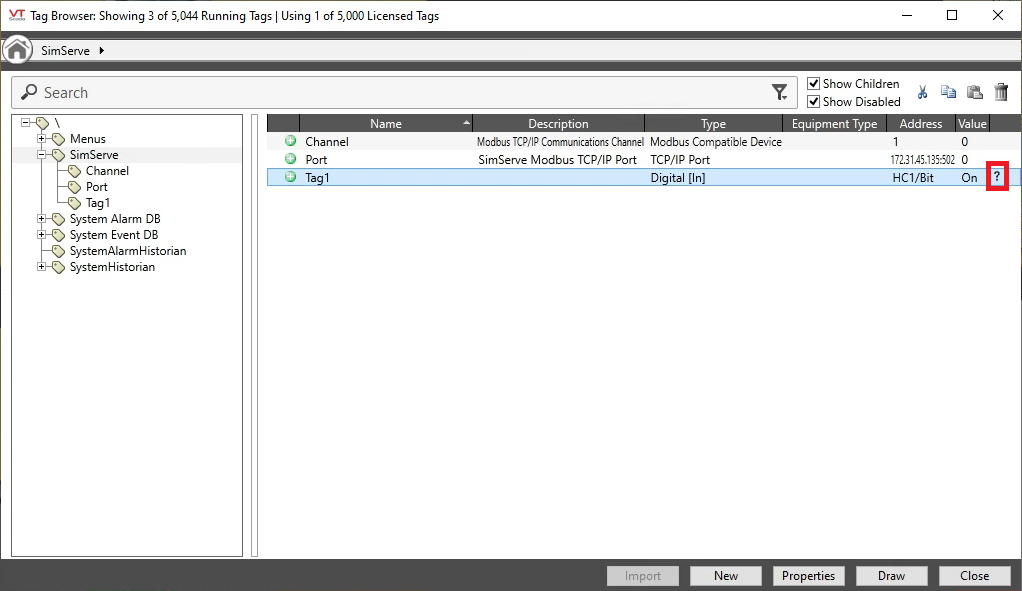
In addition to the value column, notice the “?” that appears as shown below. This means that VTScada has flagged the tag value as “questionable”. By default, all newly created tags are flagged as questionable to notify the programmer the tag needs to be tested.
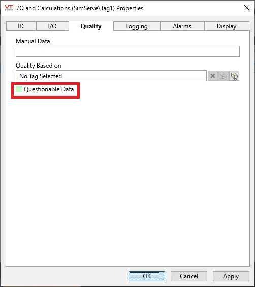
Because we just tested Tag1, we’ll turn the questionable status off. Right click on the tag, select properties, go to the “Quality” tab, and uncheck “Questionable Data” as shown below.
Lastly, we’ll link Tag1 to some graphics and view the tag value at runtime. Then, we’ll toggle the register value in SimServe and observe how the tag value in the HMI changes.
Tag 2: Boolean in 1×1 Register
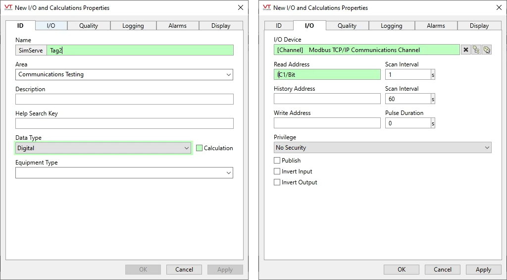
Now we’ll create a second tag, just like Tag1, except this time we’ll point the tag at discrete input register 1 (1×1). Go to the VTScada Tag Browser, create a new “Digital I/O and Calculations” tag, and fill out the “ID” and “I/O” tabs as shown below:
- ID Tab
- Name: Tag2
- Data Type: Select “Digital”. This is because a discrete input register (1x) only has a single bit.
- I/O Tab
- I/O Device: Select “Modbus TCP/IP Communications Channel” that was previously created.
- Read Address: Enter “IC1/Bit”:
- IC = “Input Coil” which is VTScada’s nomenclature for a discrete input register (1x).
- 1 = Register address 1
- Bit = Data type of the value stored in the Modbus register, which will always be Bit for a discrete input register
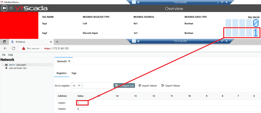
Link Tag2 to some graphics and view the tag value at runtime. Then, toggle the register value in SimServe and observe how the tag value in the HMI changes.
Tag 3: UInt16 in 3×1 Register
Now we’ll create Tag 3, and we’ll point the tag at analog input register 1 (3×1). Go to the VTScada Tag Browser, create a new “Discrete I/O and Calculations” tag, and fill out the “ID” and “I/O” tabs as shown below:
- ID Tab
- Name: Tag3
- Data Type: Select “Discrete”. This is because “Discrete” in VTScada nomenclature means integer value, and we’ll be writing an integer value to the analog input register.
- I/O Tab
- I/O Device: Select “Modbus TCP/IP Communications Channel” that was previously created.
- Read Address: Enter “IR1/UWord”:
- IR = “Input Register” which is VTScada’s nomenclature for analog input register (3x)
- 1 = Register address 1
- UWord = “Unsigned Word” which is the data type of the value we’ll be writing to the Modbus register

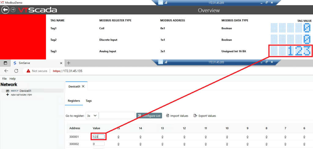
Link Tag3 to graphics in the HMI, view the HMI at runtime, and enter a unique value in register 3×1 in SimServe. Observe the correct value being displayed in the HMI.
Tag 4: UInt32 in 3×2 Register
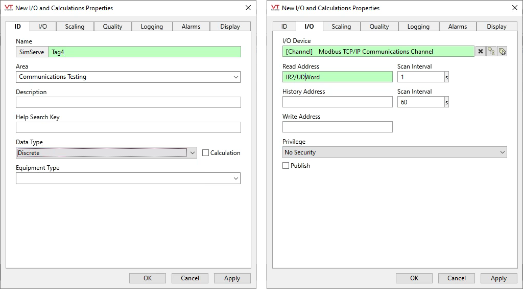
Now we’ll create Tag 4, and we’ll point the tag at analog input register 2 (3×2). Go to the VTScada Tag Browser, create a new “Discrete I/O and Calculations” tag, and fill out the “ID” and “I/O” tabs as shown below:
- ID Tab
- Name: Tag4
- Data Type: Select “Discrete”. This is because “Discrete” in VTScada nomenclature means integer value, and we’ll be writing an integer value to the analog input register.
- I/O Tab
- I/O Device: Select “Modbus TCP/IP Communications Channel” that was previously created.
- Read Address: Enter “IR2/UDWord”:
- IR = “Input Register” which is VTScada’s nomenclature for analog input register (3x)
- 2 = Register address 2
- UDWord = “Unsigned Double Word” which is the data type of the value that we’ll be writing to the Modbus register
Link Tag4 to graphics in the HMI, but wait to view in runtime.
Unlike previous tags we’ve created, this tag is more complicated. The data type we’ve specified in the item path is a 32 bit integer (UInt32). Because analog input registers are only 16 bits in size, this means VTScada will read two analog input registers, starting at 3×2 and ending at 3×3. VTScada will combine the binary bits from both registers into a single integer. This makes it difficult to manually enter register values in SimServe and verify the correct value is displayed in the HMI because VTScada is doing some math to combine registers “behind the scenes”. Luckily, SimServe has the ability to create tags and point them at registers just like VTScada! We’ll use this capability to make testing easier.
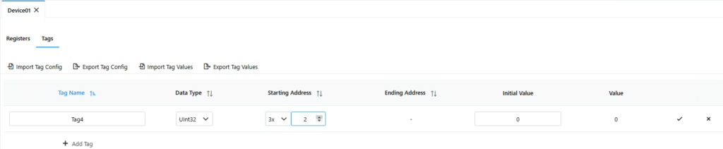
Navigate to SimServe. In the Device01 tab, click on the “Tags” tab. Click on “Add Tag” and fill out the tag form as specified. Then click the check mark:
- Tag Name: Tag4
- Data Type: UInt32
- Starting Address: 3×2
- Initial Value: 0
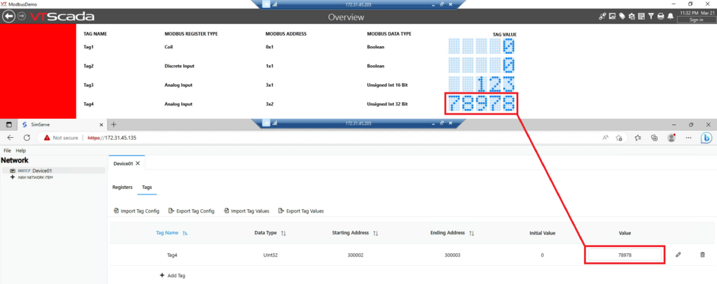
Enter a unique value for Tag4 in SimServe. Then compare the tag value in SimServe to the VTScada HMI and ensure the correct value is displayed.
Tag 5: Float in 3×4 Register
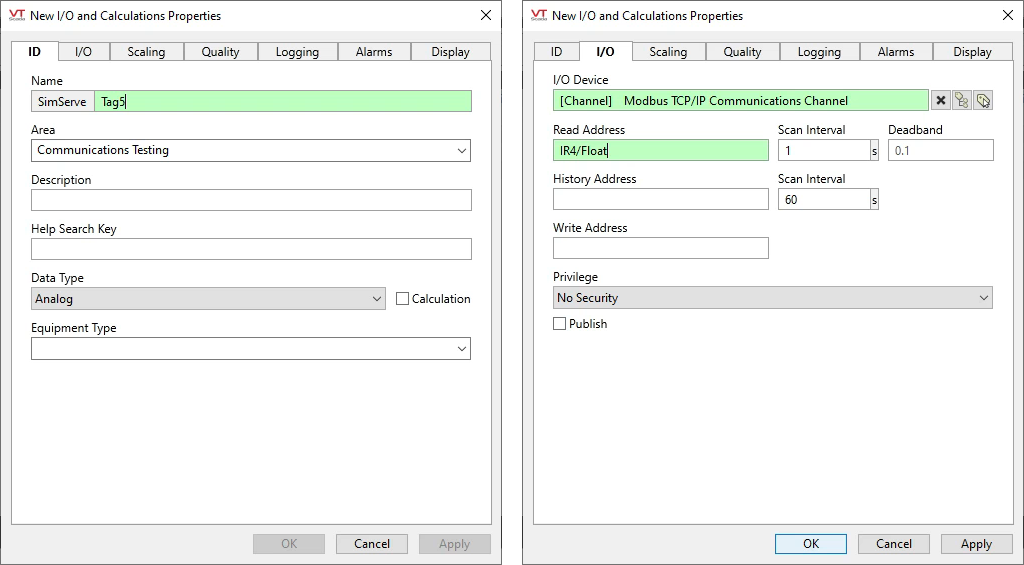
Now we’ll create Tag 5, and we’ll point the tag at analog input register 4 (3×4). Go to the VTScada Tag Browser, create a new “Analog I/O and Calculations” tag, and fill out the “ID” and “I/O” tabs as shown below:
- ID Tab
- Name: Tag5
- Data Type: Select “Analog”. This is because “Analog” in VTScada nomenclature means float value, and we’ll be writing a float value to the analog input register.
- I/O Tab
- I/O Device: Select “Modbus TCP/IP Communications Channel” that was previously created.
- Read Address: Enter “IR4/Float”:
- IR = “Input Register” which is VTScada’s nomenclature for analog input register (3x)
- 4 = Register address 4
- Float = The data type of the value we’ll be writing to the Modbus register
Link Tag5 to graphics in the HMI.
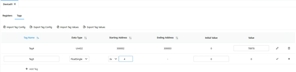
Navigate to SimServe and create Tag5 as specified:
- Tag Name: Tag5
- Data Type: FloatSingle
- Starting Address: 3×4
- Initial Value: 0
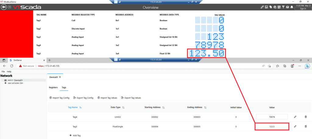
Enter a unique value for Tag5 in SimServe. Then compare the tag value in SimServe to the VTScada HMI and ensure the correct value is displayed.
Tag 6: SInt16 in 4×1 Register
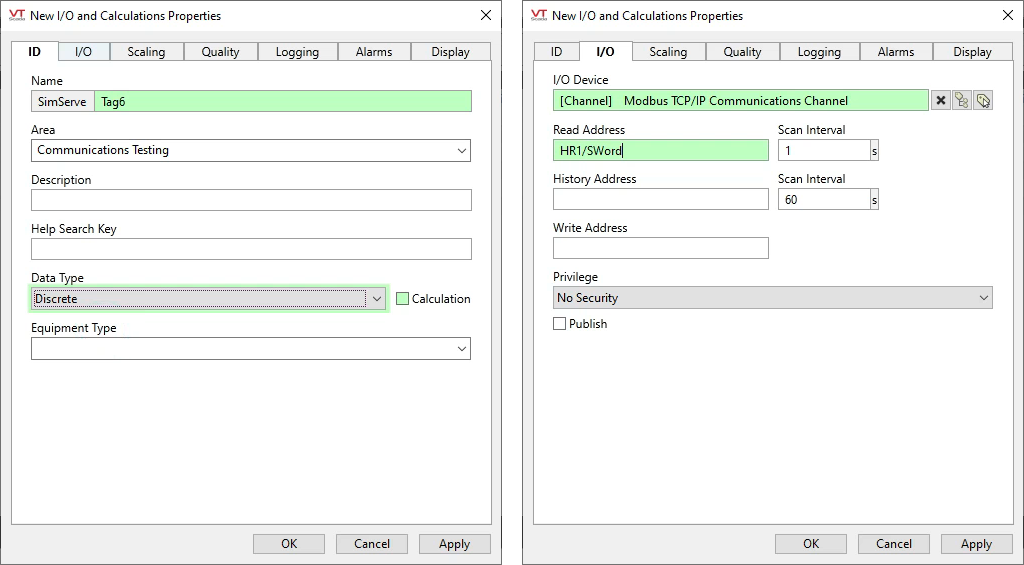
Now we’ll create Tag 6, and we’ll point the tag at holding register 1 (4×1). Go to the VTScada Tag Browser, create a new “Discrete I/O and Calculations” tag, and fill out the “ID” and “I/O” tabs as shown below:
- ID Tab
- Name: Tag6
- Data Type: Select “Discrete”. This is because “Discrete” in VTScada nomenclature means integer value, and we’ll be writing an integer value to the holding register.
- I/O Tab
- I/O Device: Select “Modbus TCP/IP Communications Channel” that was previously created.
- Read Address: Enter “HR1/SWord”:
- HR = Holding Register (4x)
- 1 = Register address 1
- SWord = “Signed Word” which is the data type of the value we’ll be writing to the Modbus register
Link Tag6 to graphics in the HMI.
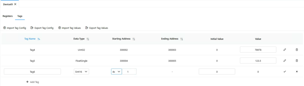
Navigate to SimServe and create Tag6 as specified:
- Tag Name: Tag6
- Data Type: SInt16
- Starting Address: 4×1
- Initial Value: 0
Enter a unique value for Tag6 in SimServe. Then compare the tag value in SimServe to the VTScada HMI and ensure the correct value is displayed.
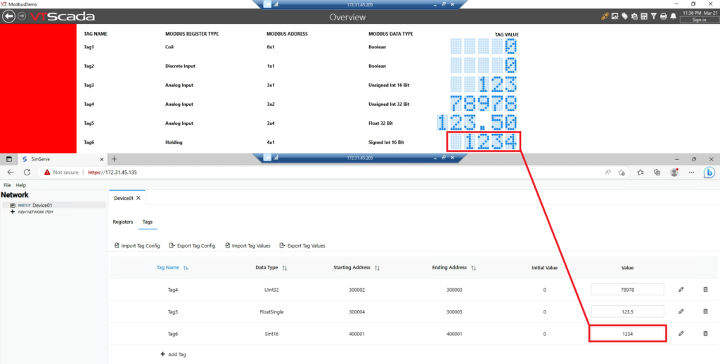
Tag 7: SInt32 in 4×2 Register
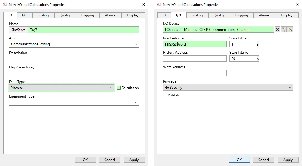
Now we’ll create Tag 7, and we’ll point the tag at holding register 2 (4×2). Go to the VTScada Tag Browser, create a new “Discrete I/O and Calculations” tag, and fill out the “ID” and “I/O” tabs as shown below:
- ID Tab
- Name: Tag7
- Data Type: Select “Discrete”. This is because “Discrete” in VTScada nomenclature means integer value, and we’ll be writing an integer value to the holding register.
- I/O Tab
- I/O Device: Select “Modbus TCP/IP Communications Channel” that was previously created.
- Read Address: Enter “HR2/SDWord”:
- HR = Holding Register (4x)
- 2 = Register address 2
- SDWord = “Signed Double Word” which is the data type of the value we’ll be writing to the Modbus register
Link Tag7 to graphics in the HMI.
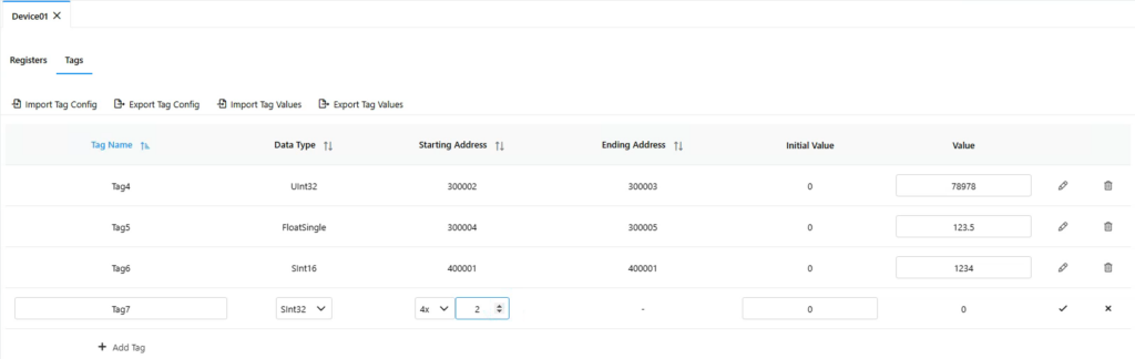
Navigate to SimServe and create Tag7 as specified:
- Tag Name: Tag7
- Data Type: SInt32
- Starting Address: 4×2
- Initial Value: 0
Enter a unique value for Tag7 in SimServe. Then compare the tag value in SimServe to the VTScada HMI and ensure the correct value is displayed.

Tag 8: FloatDouble in 4×4 Register
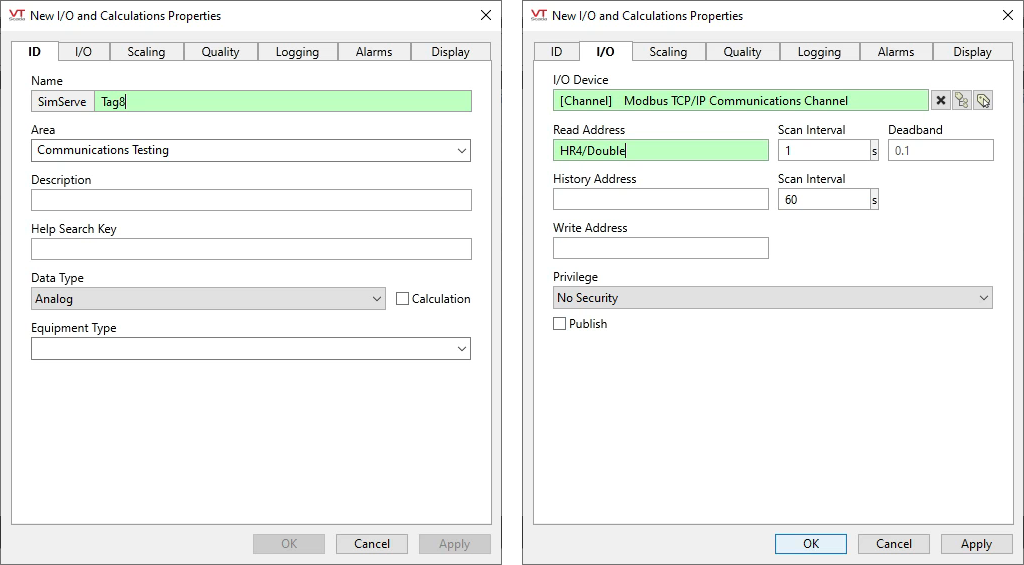
Now we’ll create Tag 8, and we’ll point the tag at holding register 4 (4×4). Go to the VTScada Tag Browser, create a new “Analog I/O and Calculations” tag, and fill out the “ID” and “I/O” tabs as shown below:
- ID Tab
- Name: Tag8
- Data Type: Select “Analog”. This is because “Analog” in VTScada nomenclature means float value, and we’ll be writing a float value to the analog input register.
- I/O Tab
- I/O Device: Select “Modbus TCP/IP Communications Channel” that was previously created.
- Read Address: Enter “HR4/Double”:
- HR = Holding Register (4x)
- 4 = Register address 4
- Double= The data type of the value we’ll be writing to the Modbus register
Link Tag8 to graphics in the HMI.
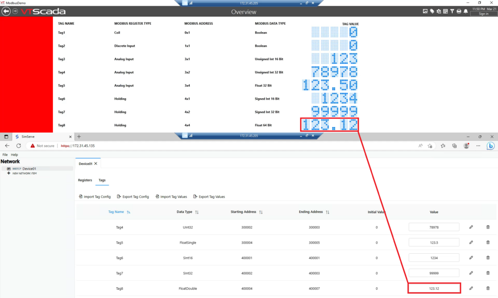
Navigate to SimServe and create Tag8 as specified:
- Tag Name: Tag8
- Data Type: FloatDouble
- Starting Address: 4×4
- Initial Value: 0
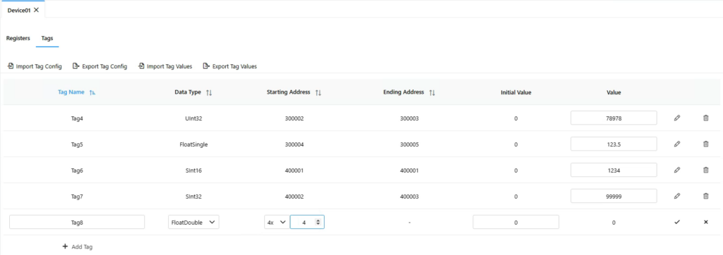
Enter a unique value for Tag8 in SimServe. Then compare the tag value in SimServe to the VTScada HMI and ensure the value is displayed.
Conclusion
So that’s the process. That’s how tags in VTScada can be linked to Modbus registers in an external device. I know there’s a lot of steps, but hopefully this video eliminates some headaches for you in your future integration work. Lastly, as the tutorial shows, SimServe is a great tool to help work through VTScada to Modbus integration challenges and I recommend checking it out. Thank you for reading, and please reach out to us at support@scadamatic.com if you have any questions we can assist with.