
In this tutorial we'll connect Ignition by Inductive Automation to a Modbus TCP/IP device. We'll set up tags in Ignition to read the Modbus registers and finish by displaying live values on an Ignition Perspective HMI.
SimServe is installed on a separate computer on the same network as Ignition, so the example mirrors a real integration.
Create the SimServe project
Start with a blank project.
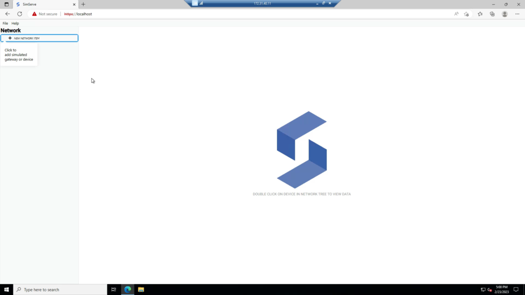
Click New Network Item and fill in:
- Name:
Device01 - Protocol:
MBTCP - IP Address:
0.0.0.0(listen on every IP) - Leave the rest as default → Save
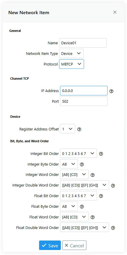
If Ignition values don't match SimServe values, revisit bit/byte/word order at the bottom of the SimServe device form.
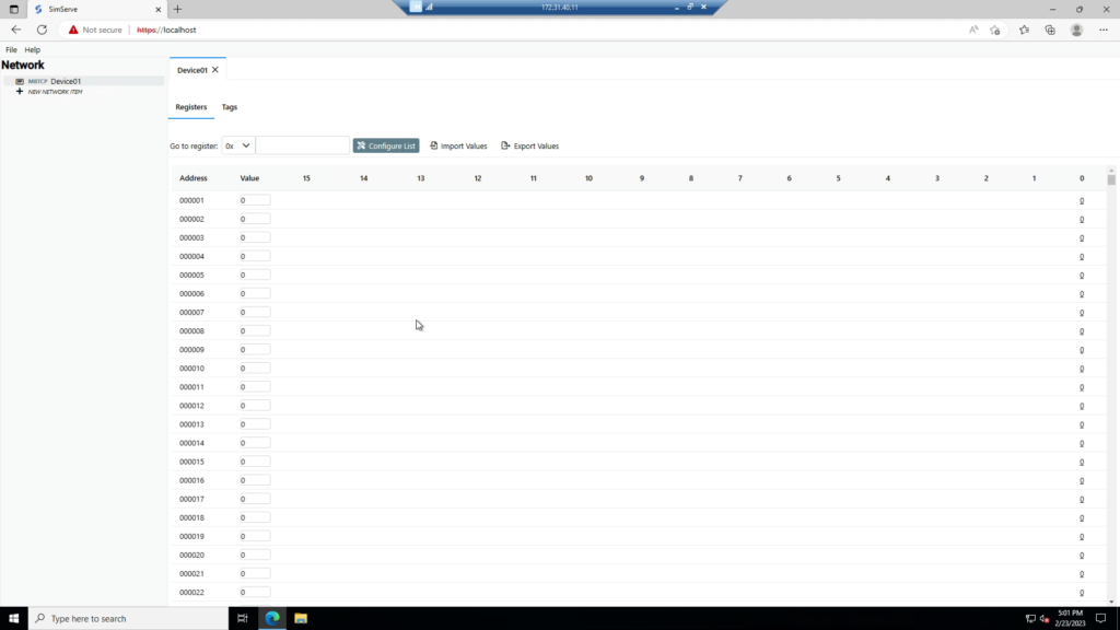
Double-click Device01 to view its registers, the device is now being simulated.
Set up the device connection in Ignition
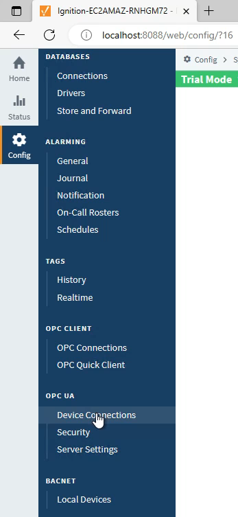
In the Ignition web UI go to Config → OPC UA → Device Connections → Create new Device. Modbus connections are proxied by Ignition's OPC UA server.
Select Modbus TCP → Next, then fill in:
- Name:
Device01(matches SimServe) - Enabled: checked
- Hostname: IP of the SimServe host (e.g.
172.31.40.11) - Port:
502
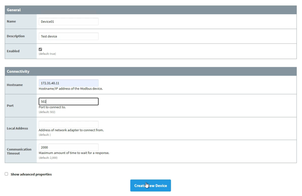
Confirm the status column shows connected before continuing.

Create Ignition tags and test
Create OPC tags in the tag browser (+ → New Standard Tag → OPC Tag) using the Ignition OPC UA Server. The OPC Item Path syntax is what links each tag to a specific Modbus register.
Tag 1, Boolean in 0x1 (coil)
- Data Type: Boolean
- OPC Item Path:
[Device01]C1C= Coil (0x),1= address 1
Toggle 0x1 in SimServe and confirm the tag flips in Ignition.
Tag 2, Boolean in 1x1 (discrete input)
- Data Type: Boolean
- OPC Item Path:
[Device01]DI1DI= Discrete Input (1x)
Tag 3, UInt16 in 3x1 (input register)
- Data Type: Integer
- OPC Item Path:
[Device01]IR1IR= Input Register (3x)
Tag 4, UInt32 in 3x2
- Data Type: Integer
- OPC Item Path:
[Device01]IRUI2UI= Unsigned Integer (UInt32), spans registers3x2and3x3
Create a matching Tag in SimServe (UInt32, starting address 3x2) for easy verification, since Ignition combines two 16-bit registers into one integer.
Tag 5, Float in 3x4
- Data Type: Float
- OPC Item Path:
[Device01]IRF4 - In SimServe:
FloatSingle, starting address3x4.
Tag 6, SInt16 in 4x1 (holding register)
- Data Type: Integer
- OPC Item Path:
[Device01]HR1HR= Holding Register (4x)
Tag 7, SInt32 in 4x2
- Data Type: Integer
- OPC Item Path:
[Device01]HRI2I= Signed Integer (SInt32)
Tag 8, FloatDouble in 4x4
- Data Type: Double
- OPC Item Path:
[Device01]HRD4 - In SimServe:
FloatDouble, starting address4x4.
Wrap up
Reference for the full Modbus addressing syntax lives in the Ignition user manual under Modbus Addressing. With SimServe standing in for the PLC, you can prove out an Ignition tag map before a single wire is landed in the field.