
In this tutorial we'll connect VTScada by Trihedral to a Modbus TCP/IP device. We'll set up tags in VTScada to read the Modbus registers in the device and finish by displaying live tag values on a VTScada HMI screen.
To make the example realistic, SimServe is installed on a separate computer connected to the same network as VTScada.
Create the SimServe project
Start with a blank project in SimServe.

Click New Network Item and fill out the form:
- Name:
Device01 - Protocol:
MBTCP(Modbus TCP) - IP Address:
0.0.0.0, the device listens on every IP assigned to the host - Set bit order, byte order, word order, and double-word order for integers and floats
- Leave the remaining fields as default
- Click Save
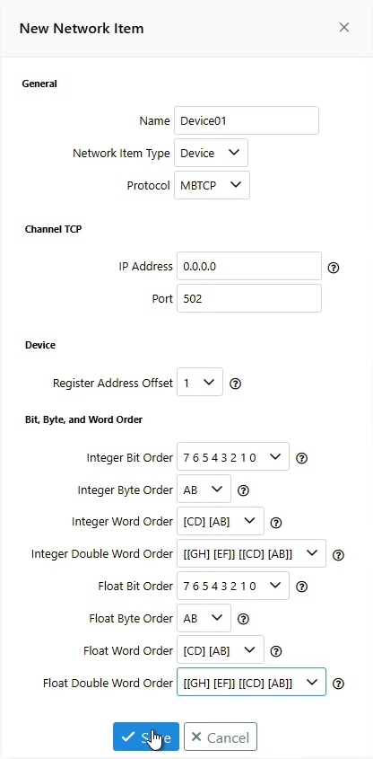
If VTScada values don't match the values you enter in SimServe, revisit bit/byte/word order, the two hosts may differ.
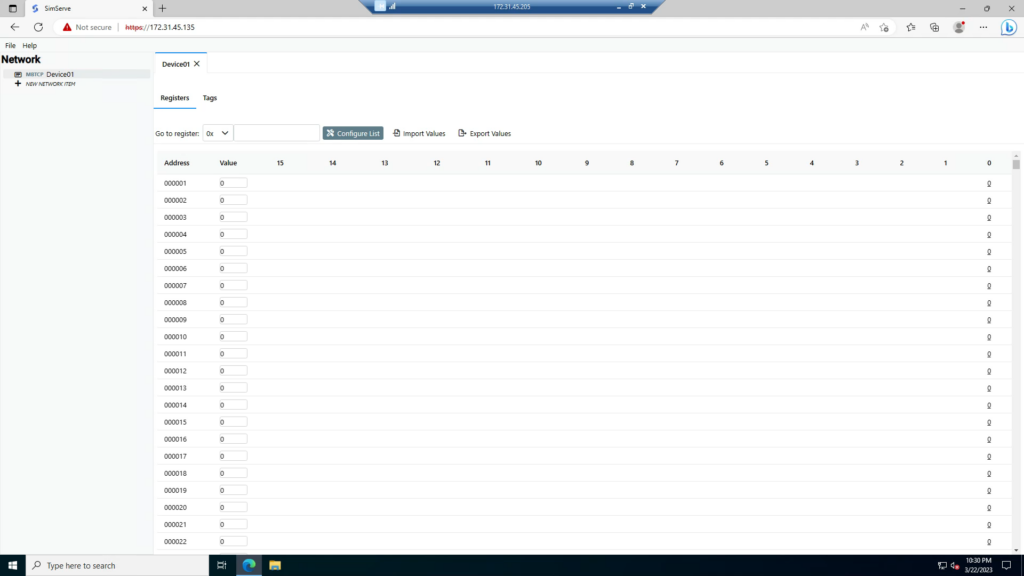
The device appears in the network tree. Double-click Device01 to view the Modbus registers, SimServe is now simulating it.
Set up the device connection in VTScada
Launch VTScada and open (or create) an application. In the Tag Browser, create a new Context called SimServe to hold everything.
Communications chain
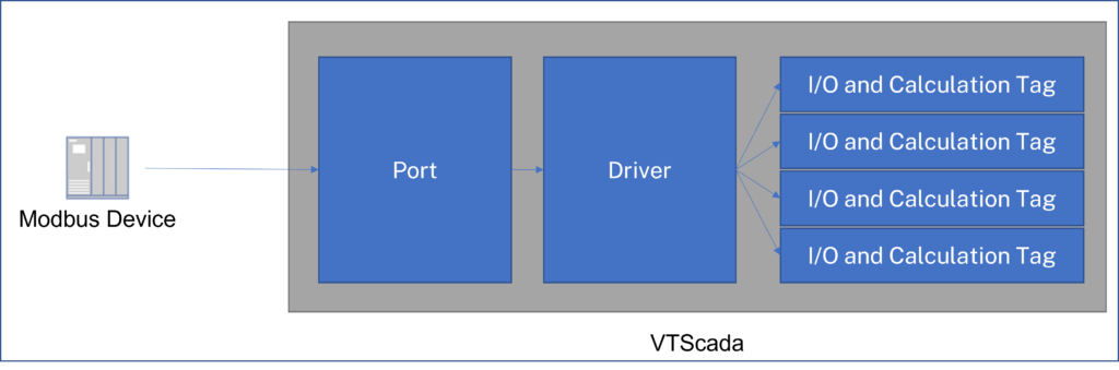
A VTScada communications chain has three links:
- Port, how VTScada reaches the physical device
- Driver, the protocol and any protocol-specific settings
- I/O and Calculation Tags, hold references to the memory registers
Data flows: Device → Port → Driver → Tags.
Create the Port
Right-click the SimServe context → New Child → Ports → TCP/IP Port.
- Name:
Port - Description:
SimServe Modbus TCP/IP Port - TCP/IP Name/Address: the IP address of the SimServe host (e.g.
172.31.45.135) - Port:
502
Create the Driver
Right-click SimServe → New Child → Driver → Modbus Compatible Device.
- Name:
Channel - Description:
Modbus TCP/IP Communications Channel - Comm Channel:
Open Modbus TCP - Port: the
SimServe Modbus TCP/IP Portcreated above
Create VTScada tags and test
Now create tags pointed at specific Modbus registers in Device01, link them to graphics, and verify runtime values against SimServe.
Tag 1, Boolean in 0x1 (coil)
Digital I/O and Calculations tag.
- Name:
Tag1 - I/O Device:
Modbus TCP/IP Communications Channel - Read Address:
HC1/BitHC= Holding Coil (VTScada's name for coil register0x)1= address 1Bit= data type
Toggle 0x1 in SimServe and confirm the tag flips in VTScada. New tags are flagged Questionable by default; clear it under Properties → Quality once you've verified.
Tag 2, Boolean in 1x1 (discrete input)
- Name:
Tag2 - Read Address:
IC1/BitIC= Input Coil (VTScada's name for discrete input1x)
Tag 3, UInt16 in 3x1 (input register)
Discrete I/O and Calculations tag.
- Read Address:
IR1/UWordIR= Input Register (3x)UWord= Unsigned Word
Tag 4, UInt32 in 3x2
- Read Address:
IR2/UDWord
A UInt32 spans two 16-bit input registers (3x2 and 3x3), VTScada does the math behind the scenes. Rather than entering raw register bytes in SimServe, create a matching Tag in SimServe (Data Type UInt32, Starting Address 3x2) and enter values there. This makes verification trivial.
Tag 5, Float in 3x4
- Read Address:
IR4/Float - In SimServe: Data Type
FloatSingle, Starting Address3x4.
Tag 6, SInt16 in 4x1 (holding register)
- Read Address:
HR1/SWord - In SimServe: Data Type
SInt16, Starting Address4x1.
Tag 7, SInt32 in 4x2
- Read Address:
HR2/SDWord - In SimServe: Data Type
SInt32, Starting Address4x2.
Tag 8, FloatDouble in 4x4
- Read Address:
HR4/Double - In SimServe: Data Type
FloatDouble, Starting Address4x4.
Wrap up
That covers every common Modbus data type against every register class. Once VTScada's tag values match SimServe's, your communications chain is proven, swap SimServe for the real PLC when the field is ready.